Binary Encoder and Decoder
Binary Encoder and Decoder

In this article we will discuss about the construction and operation of the binary encoder and decoder with logic diagrams and truth tables.
Binary Encoder
A Digital Encoder more commonly known as a Binary Encoder takes all its data inputs one at a time and then converts them into a single encoded output.
We can say that a binary encoder, is a multi-input combinational logic circuit that converts the logic level “1” data at its inputs into an equivalent binary code at its output.
An “n-bit” binary encoder has 2n input lines and n-bit output lines such as 4-to-2, 8-to-3 and 16-to-4 line configurations.
The output lines of a digital encoder generate the binary equivalent of the input line whose value is equal to “1” and are available to encode either a decimal or hexadecimal input pattern to typically a binary or “BCD” (binary coded decimal) output code.
4-to-2 Bit Binary Encoder

Fig.1
One of the main disadvantages of standard digital encoders is that they can generate the wrong output code when there is more than one input present at logic level “1”. For example, if we make inputs D1 and D2 HIGH at logic “1” both at the same time, the resulting output is neither at “01” or at “10” but will be at “11” which is an output binary number that is different to the actual input present. Also, an output code of all logic “0”s can be generated when all of its inputs are at “0” OR when input D0 is equal to one.
One simple way to overcome this problem is to add Priority to the level of each input pin and if there was more than one input at logic level “1” the actual output code would only correspond to the input with the highest designated priority. Then this type of digital encoder is known commonly as a Priority Encoder or P-encoder for short.
Priority Encoder
The Priority Encoder solves the problems mentioned above by allocating a priority level to each input.
The priority encoders output corresponds to the currently active input which has the highest priority.
So when an input with a higher priority is present, all other inputs with a lower priority will be ignored.
The priority encoder comes in many different forms with an example of an 8-input priority encoder along with its truth table shown below.
8-to-3 Bit Priority Encoder

Fig.2
Priority encoders are available in standard IC form.
The TTL 74LS148 is an 8-to-3 bit priority encoder which has eight active LOW (logic “0”) inputs and provides a 3-bit code of the highest ranked input at its output.
Priority encoders output the highest order input first for example, if input lines “D2“, “D3” and “D5” are applied simultaneously the output code would be for input “D5” (“101″) as this has the highest order out of the 3 inputs. Once input “D5” had been removed the next highest output code would be for input “D3” (“011″), and so on.
The truth table for a 8-to-3 bit priority encoder is given as:

Fig.3
Where X equals “don’t care”, i.e. logic “0” or a logic “1”.
From this truth table, the Boolean expression for the encoder above with data inputs D0 to D7 and outputs Q0, Q1, Q2 is given as:
Output Q0:
![]()
![]()
![]()
![]()
Output Q1:
![]()
![]()
![]()
![]()
Output Q2:
![]()
![]()
![]()
We can constructed a simple encoder from the expression above using individual OR gates as follows.
Digital Encoder using Logic Gates

Fig.4
Binary Decoder
The Binary Decoder is a combinational logic circuit that is the exact opposite to that of an Encoder.
The name “Decoder” means to translate or decode coded information from one format into another, so a digital decoder transforms a set of digital input signals into an equivalent decimal code at its output.
A decoder generally decodes a binary value into a non-binary one by setting exactly one of its n outputs to logic “1”.
If a binary decoder receives n inputs (usually grouped as a single Binary or Boolean number) it activates one and only one of its 2n outputs based on that input with all other outputs deactivated.
We can say that a standard combinational logic decoder is an n-to-m decoder, where m ≤ 2n, and whose output, Q is dependent only on its present input states.
In other words, a binary decoder looks at its current inputs, determines which binary code or binary number is present at its inputs and selects the appropriate output that corresponds to that binary input.
Commonly available BCD-to-Decimal decoders include the TTL 7442 or the CMOS 4028.
Generally a decoder output code normally has more bits than its input code and practical “binary decoder” circuits include, 2-to-4, 3-to-8 and 4-to-16 line configurations.
An example of a 2-to-4 line decoder along with its truth table is given below.
A 2-to-4 Binary Decoder

Fig.5

Fig.6
This simple example of a 2-to-4 line binary decoder consists of an array of four AND gates.
The 2 binary inputs labeled A and B are decoded into one of 4 outputs. Each output represents one of the minterms of the 2 input variables.
The binary inputs A and B determine which output line from Q0 to Q3 is “HIGH” at logic level “1” while the remaining outputs are held “LOW” at logic “0”. So only one output can be active (HIGH) at any one time.
Therefore, whichever output line is “HIGH” identifies the binary code present at the input, in other words it “de-codes” the binary input.
Some binary decoders have an additional input pin labeled “Enable” that controls the outputs from the device. This extra input allows the decoders outputs to be turned “ON” or “OFF” as required. These types of binary decoders are commonly used as “memory address decoders” in microprocessor memory applications.
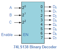
Fig.7
We can say that a binary decoder is a de-multiplexer with an additional data line that is used to enable the decoder.
An alternative way of looking at the decoder circuit is to regard inputs A, B and C as address signals. Each combination of A, B or C defines a unique memory address.