Binary Counters
Last Updated on September 27, 2015 by Sasmita
Binary Counters
Normally binary counters are used for counting the number of pulses coming at the input line in a specified time period.
The binary counters must possess memory since it has to remember its past states.
As the name suggests, it is a circuit which counts.The main purpose of the counter is to record the number of occurrence of some input.
-
Asynchronous (Ripple) Counters – The first flip-flop is clocked by the external clock pulse, and then each successive flip-flop is clocked by the Q or Q’ output of the previous flip-flop.
-
Synchronous Counters – All memory elements are simultaneously triggered by the same clock.
Asynchronous or Ripple Counters
A two-bit asynchronous counter is shown below in fig.1. The toggle(T) flip-flops are being used. But we can use the JK flip-flop also with J and K connected permanently to logic 1.

Fig.1
The external clock is connected to the clock input of the first flip-flop (FF-A) only and QA output is applied to the clock input of the next flip-flop i.e. FF-B.
So, FF-A changes state at the falling edge of each clock pulse, but FF-B changes only when triggered by the falling edge of the QA output of FF-A.
Because of the inherent propagation delay through a flip-flop, the transition of the input clock pulse and a transition of the QA output of FF-A can never occur at exactly the same time.
Therefore, the flip-flops cannot be triggered simultaneously, producing an asynchronous operation.
Operation
Initially let both the Flip-flops be in the reset state i.e QAQA= 00
After 1st negative clock edge:
- As soon as the first negative clock edge is applied to FF-A, QA will be equal to 1.
- QA is connected to clock input of FF-B. Since QA has changed from 0 to 1, it is treated as the positive clock edge by FF-B. So, there is no change in QB because FF-B is a negative edge triggered FF.
Hence, QBQA = 01…………….After the first clock pulse
After 2nd negative clock edge:
- On the arrival of second negative clock edge, FF-A toggles again and QA = 0.
- The change in QA acts as a negative clock edge for FF-B. So it will also toggle, and QB will be 1.
Hence, QBQA = 10…………….After the second clock pulse
After 3rd negative clock edge:
- On the arrival of 3rd negative clock edge, FF-A toggles again and QA become 1 from 0.
- Since this is a positive going change,FF-B does not respond to it and remains inactive. So QB does not change and continues to be equal to 1.
Hence, QBQA = 11…………….After the third clock pulse
After 4th negative clock edge:
- On the arrival of 4th negative clock edge, FF-A toggles again and QA become 1 from 0.
- This negative change in QA acts as clock pulse for FF-B. Hence it toggles to change QB from 1 to 0.
Hence, QBQA = 00…………….After the fourth clock pulse
Truth Table


Synchronous counters
If the “clock” pulses are applied to all the flip-flops in a counter simultaneously, then such a counter is called as synchronous counter.
2-Bit Synchronous UP Counter
The JA and KA inputs of FF-A are tied to logic 1. So FF-A will work as a toggle flip-flop. The JB and KB inputs are connected to QA.
Logic Diagram

Fig.2
Operation
Initially let both the FFs be in the reset state:
QBQA = 00…………….initially
After 1st negative clock edge
- As soon as the first negative clock edge is applied, FF-A will toggle and QA will change from 0 to 1.
- But at the instant of application of negative clock edge, QA ,JB = KB =0 Hence FF-B will not change its state. So QB will remain 0.
Hence, QBQA = 01…………….After the first clock pulse
After 2nd negative clock edge
- On the arrival of second negative clock edge, FF-A toggles again and QA change from 1 to 0.
- But at this instant QA was 1. So JB = KB=1 and FF-B will toggle. Hence QB changes from 0 to 1.
Hence, QBQA = 10…………….After the second clock pulse
After 3rd negative clock edge
- On application of the third falling clock edge, FF-A will toggle from 0 to 1 but there is no change of state for FF-B.
Hence, QBQA = 11…………….After the third clock pulse
After 4th negative clock edge
- On application of the next clock pulse, QA will change from 1 to 0 as QB will also change from 1 to 0.
Hence, QBQA = 00…………….After the fourth clock pulse
Classification of counters
Depending on the way in which the counting progresses, the synchronous or asynchronous counters are classified as follows.
- Up counters
- Down counters
- Up/Down counters
UP/DOWN Counter
In the up/down counter, up counter and down counter are combined together to obtain an UP/DOWN counter.
A mode control (M) input is also provided to select either up or down mode.
A combinational circuit is required to be designed and used between each pair of flip-flop in order to achieve the up/down operation.
Type of up/down counters:
- UP/DOWN ripple counters
- UP/DOWN synchronous counters
UP/DOWN Ripple Counters
In the UP/DOWN ripple counter all the FFs operate in the toggle mode.
So either T flip-flops or JK flip-flops are to be used.
The LSB flip-flop receives clock directly. But the clock to every other FF is obtained from (Q or Q bar) output of the previous FF.
- UP counting mode (M=0): The Q output of the preceding FF is connected to the clock of the next stage if up counting is to be achieved. For this mode, the mode select input M is at logic 0 (M=0).
- DOWN counting mode (M=1) : If M =1, then the Q bar output of the preceding FF is connected to the next FF. This will operate the counter in the down counting mode.
EXAMPLE
3-bit binary up/down ripple counter.
- 3-bit : hence three FFs are required.
- UP/DOWN : So a mode control input is essential.
- For a ripple up counter, the Q output of preceding FF is connected to the clock input of the next one.
- For a ripple down counter, the Q bar output of preceding FF is connected to the clock input of the next one.
- Let the selection of Q and Q bar output of the preceding FF be controlled by the mode control input M such that, If M = 0, UP counting. So connect Q to CLK. If M = 1, DOWN counting. So connect Q bar to CLK.
BLOCK DIAGRAM

Fig.3

Fig.4
TRUTH TABLE

OPERATION
Case 1: With M = 0 (Up counting mode)
- If M = 0 and M bar = 1, then the AND gates 1 and 3 in fig. will be enabled whereas the AND gates 2 and 4 will be disabled.
- Hence QA gets connected to the clock input of FF-B and QB gets connected to the clock input of FF-C.
- These connections are same as those for the normal up counter. Thus with M = 0 the circuit work as an up counter.
Case 2: With M = 1 (Down counting mode)
- If M = 1, then AND gates 2 and 4 in fig. are enabled whereas the AND gates 1 and 3 are disabled.
- Hence QA bar gets connected to the clock input of FF-B and QB bar gets connected to the clock input of FF-C.
- These connections will produce a down counter. Thus with M = 1 the circuit works as a down counter.
UP/DOWN Synchronous Counter
Example: Synchronous 3-bit Up/Down Counter
Block Diagram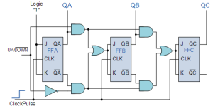
Fig.5
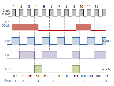
The circuit above is of a simple 3-bit Up/Down synchronous counter using JK flip-flops configured to operate as toggle or T-type flip-flops giving a maximum count of zero (000) to seven (111) and back to zero again.
Hence, the 3-Bit counter advances upward in sequence (0,1,2,3,4,5,6,7) or downwards in reverse sequence (7,6,5,4,3,2,1,0).
Modulus Counter (MOD-N Counter)
The 2-bit ripple counter is called as MOD-4 counter and 3-bit ripple counter is called as MOD-8 counter. So in general, an n-bit ripple counter is called as modulo-N counter. Where,MOD number = 2n
TYPE OF MODULUS
- 2-bit up or down (MOD-4)
- 3-bit up or down (MOD-8)
- 4-bit up or down (MOD-16)
Application of the counters
- Frequency counters
- Digital clock
- Time measurement
- A to D converter
- Frequency divider circuits
- Digital triangular wave generator