Binary Subtractor
Last Updated on September 27, 2015 by Sasmita
The Binary Subtractor
Binary Subtractor is another type of combinational arithmetic circuit that is used to subtract two binary numbers from each other, for example, X – Y to find the resulting difference between the two numbers.
Unlike the Binary Adder which produces a SUM and a CARRY bit when two binary numbers are added together, the binary Subtractor produces a DIFFERENCE, D by using a BORROW bit, B from the previous column. The operation of subtraction is the opposite to that of addition.
A Half Subtractor Circuit
A half subtractor is a logical circuit that performs a subtraction operation on two binary digits. The half subtractor produces a difference and a borrow bit for the next stage.
Half Subtractor with Borrow-out
The block diagram of a half Subtractor is shown below in fig.1. The symbol and truth table are shown in fig.2.

Fig.1
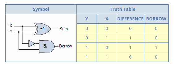
Fig.2
From the truth table of the half subtractor we can see that the DIFFERENCE (D) output is the result of the Exclusive-OR gate and the Borrow-out (Bout) is the result of the NOT-AND combination.
The Boolean expression for a half subtractor is as follows:
For the DIFFERENCE bit:
![]()
For the BORROW bit:
![]()
One major disadvantage of the Half Subtractor circuit when used as a binary subtractor, is that there is no provision for a “Borrow-in” from the previous circuit when subtracting multiple data bits from each other. Then we need to produce a full subtractor circuit to take into account this borrow-in input.
A Full Subtractor Circuit
The main difference between the Full Subtractor and the previous Half Subtractor circuit is that a full subtractor has three inputs.
The two single bit data inputs X (minuend) and Y (subtrahend) the same as before plus an additional Borrow-in (BIN) input to receive the borrow generated by the subtraction process from a previous stage as shown below.
Full Subtractor Block Diagram
 Fig.3
Fig.3
The combinational circuit of a full subtractor performs the operation of subtraction on three binary bits producing outputs for the difference D and borrow BOUT .
Just like the binary adder circuit, the full subtractor can also be thought of as two half subtractors connected together, with the first half subtractor passing its borrow to the second half subtractor as follows.
Full Subtractor Logic Diagram

Fig.4
The truth table for the full subtractor is given below:
Full Subtractor Truth Table
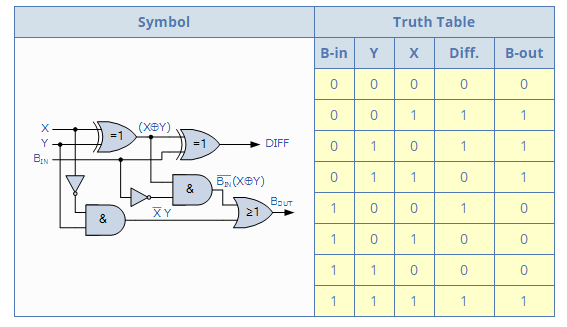
Fig.5
Hence the Boolean expression for a full subtractor is as follows:
For the DIFFERENCE (D) bit:
![]()
For the BORROW OUT (Bout) bit:
![]()
An n-bit Binary Subtractor
As with the binary adder, we can also have n number of 1-bit full subtractors connected or “cascaded” together to subtract two parallel n-bit numbers from each other.
For example take two 4-bit binary numbers.
So by using an n-bit adder and n number of inverters (NOT Gates), the process of subtraction becomes an addition as we can use two’s complement notation on all the bits in the subtrahend and setting the carry input of the least significant bit to a logic “1” (HIGH).
Binary Subtractor using 2’s Complement
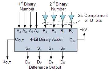
Fig.6