Coherent Binary Amplitude Shift Keying
Last Updated on June 17, 2018 by Jhasketan Garud
Amplitude Shift Keying
Definition
Amplitude Shift Keying (ASK) or ON-OFF keying(OOK) is the simplest digital modulation technique. In this method, there is only one unit energy carrier and it is switched on or off depending upon the input binary sequence.
Expression and Waveforms
The ASK waveform can be represented as:
![]()
To transmit symbol ‘0’ , the signal s(t) =0, i.e., no signal is transmitted.
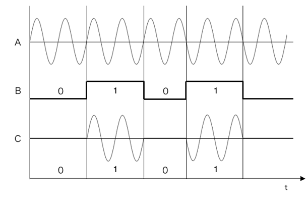
Fig.1 : Amplitude Shift Keying Waveforms, (A) Unmodulated carrier (B) NRZ Unipolar bit sequence
(C) ASK waveform
The ASK waveform looks like an ON-OFF of the signal. therefore, it is also known as ONP-FF keying (OOK).
Fig.1 shows the ASK waveform.Here Fig.1 (A) shows the unmodulated carrier wave , Fig.1 (B) shows the input data and Fig.1 (C) shows the ASK waveform.
ASK Modulator
ASK signal may be generated by simply applying the incoming data( represented in unipolar form) and the sinusoidal carrier to the two inputs of a product modulator or balanced modulator.
Fig.2 shows the block diagram of a ASK modulator.
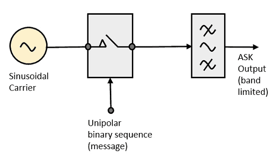
Fig.2 : ASK Modulator
It consists of the carrier signal generator, the binary sequence from the message signal and the band-limited filter.
The carrier generator, sends a continuous high-frequency carrier.
The binary sequence from the message signal makes the unipolar input to be either High or Low.
The high signal closes the switch, allowing a carrier wave. Hence, the output will be the carrier signal at high input.
When there is low input, the switch opens, allowing no voltage to appear. Hence, the output will be low.
The band-limiting filter, shapes the pulse depending upon the amplitude and phase characteristics of the band-limiting filter or the pulse-shaping filter.
ASK Demodulator
There are two types of ASK Demodulation techniques. Such as:
- Asynchronous ASK Demodulation
- Synchronous ASK Demodulation
The clock frequency at the transmitter when matches with the clock frequency at the receiver, it is known as a Synchronous method, as the frequency gets synchronized. Otherwise, it is known as Asynchronous.
Asynchronous ASK Demodulator
Fig.3 shows the block diagram of asynchronous ASK detector.
It consists of a half-wave rectifier, a low pass filter, and a comparator.

Fig.3 : Asynchronous ASK Demodulator
When the ASK signal pass through the rectifier, we can obtain the positive half wave signal. After that the signal will pass through a low-pass filter and obtain an envelop detection. Then get rid of the DC signal, the digital signal will be recurred.
Synchronous ASK Demodulator
The block diagram of a Synchronous ASK Detector is shown in Fig.4 below.
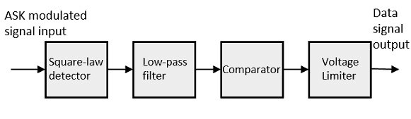
Fig.4: Synchronous ASK Demodulator
It consists of a Square law detector, low pass filter, a comparator, and a voltage limiter.
The ASK modulated input signal is given to the Square law detector.A square law detector is one whose output voltage is proportional to the square of the amplitude modulated input voltage.
The low pass filter minimizes the higher frequencies.
The comparator and the voltage limiter help to get a clean digital output.