Difference Between Rigid PCBs and Flexible PCBs
Last Updated on July 7, 2018 by Sasmita
Whenever we use the term “PCB”, normally a picture of a rigid PCB (printed circuit board) comes to our mind. However, a PCB can be either a rigid PCB or a flexible PCB.
Flexible PCBs are more commonly known as flex circuits, flex boards, flexible circuit boards, flexible printed circuit boards and, more officially, flexible electronics.

Fig.1 Flex PCB
Flex circuits have recently gained huge popularity due to the fact that they can be shaped, bent, twisted, and folded into limitless configurations.
Both the rigid PCBs and flexible PCBs however serve the same ultimate function, which is connecting various electrical and mechanical components together.
When to Use Rigid PCB and When to Use Flexible PCB
If we compare the price of Rigid PCB and Flex PCB, Rigid PCBs typically cost less than flex circuits.
“Typically” because if we consider the total cost of ownership there are some applications that, when using flexible PCBs, may be less expensive as compared to using rigid PCBs.
The flex circuits eliminate the need for some components such as connectors, wire harnesses, and other circuit boards. So by removing these components from a design, material cost, labor and assembly cost, and scrap cost are all reduced.
Many electronic devices (laptop and desktop computers,audio keyboards, solid-state drivers (SSDs), flat-screen TVs and monitors, children’s toys, and various electronic gadgets) employ rigid PCBs instead of flexible PCBs.
However, flex circuits may be found in ultra-compact and/or high-performance devices, including GPS units, tablets, smart phones, cameras, and wearables. It is also found in some low-tech applications such as under-the-counter LED lights .
It is also possible to use a flex circuit and a rigid circuit together—as a unified PCB . This approach, perhaps, provides the best of both worlds.

Figure 2. A PCB design consisting of both rigid and flexible PCBs
Here are some common terminology used for both

Difference between Rigid PCB and Flex PCB
The first and the obvious difference is : A flexible circuit can bend , fold and twist, where a rigid PCB can not.This key difference requires a flex to be manufactured with a different set of materials, design rules and different manufacturing processes.
Actually the biggest difference lies in the material.
Both PCBs and flexible circuits have similar construction. In case of a single sided circuit, the construction is dielectric base layer, adhesive layer, copper or conductive material layer and perhaps a protective overlay material.
Base layer:
For a PCB the base layer tends to be rigid and usually contains glass reinforcement. FR4 is probably the most common material. This gives the material excellent dimension stability, thermal resistance and mechanical strength, but very little ability to bend.
Flexible circuit base material are most commonly made of polymide. The material has excellent flexibility properties. But it does not have the same mechanical support for components and is less stable than FR4.
Adhesive Layer :
Since PCB doesnot bend, the requirements on the adhesive are limited to chemical and thermal properties.
However, a flexible circuit has an additional requirement to allow bending.
An adhesive that works well for a hard board, would crack in a flex application. Hence, an adhesive for a flexible circuit need to stretch a bit.
Therefore, an adhesive for a flex will have different thermal, chemical and mechanical properties than from adhesive used in PCBs.
Copper Layer :
There are basically two types of copper film, such as : Electro Deposited (ED) and Rolled Annealed (RA).
Between these two the RA copper is much more flexible and is needed in dynamic flex applications.
ED copper is almost exclusively used to produce rigid PCBs. However, it does have some flexibility and may be used in some circumstances.
There is also a High Ductility Electro Deposited (HDED) copper that is electro-deposited with a treatment that makes it more flexible, but not as good as RA.
Now if we consider the manufacturing process of both Rigid PCBs and Flex circuits, both of these have almost same manufacturing process steps. Such as the drilling and plating of holes and vias, photo imaging and development, the etching of copper traces, pads, outlines, and planes, and the heating (baking) of the circuit boards for the purpose of removing moisture from the PCBs.
However,after this point, the rigid PCBs head to the solder mask station while flex circuits go to the coverlay station.
Flex Circuit Overlay
Flex circuit overlay, also known as coverlay, is a lamination process used for encapsulating and protecting the external circuitry of a flex circuit.

Fig.3: Flex Circuit with Coverlay
A flex circuit’s coverlay film is similar to a rigid PCB’s solder mask, with one big difference i.e.,the coverlay film is flexible here in this case.
The coverlay film is generally a polyimide film that is coated with a thermoset adhesive.
Film thicknesses range from .0005” to .005” with .001” and .002” the most common.”
The polyimide and adhesive coverlay is laminated using pressure and heat, where the heat helps the adhesive to easily flow and fill in any gaps between traces and pads.
This prevents the trapping of air between the layers. The adhesive will tend to ooze out slightly around the openings shown in the diagram below. This oozing is commonly referred to as ‘adhesive squeeze out’ and is actually a desired phenomenon.
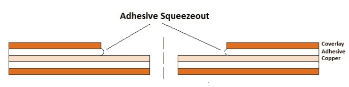
Fig.4: Flex circuit coverlay adhesive squeeze out
Once the coverlay lamination process is finished, any component and/or feature openings are made using drilling, routing, or laser cutting only as etching cannot be used anymore.
IPC Standards for Rigid and Flexible PCBs
The list of IPC standards for rigid PCBs and flex circuits are given below.
- IPC-2221A, Generic Standard on Printed Board Design
- IPC-2223, Sectional Design Standard for Flexible Printed Boards
- IPC-4101, Specification for Base Materials for Rigid and Multilayer Printed Boards
- IPC-4202, Flexible Base Dielectrics for Use in Flexible Printed Circuitry
- IPC-4203, Adhesive Coated Dielectric Films for Use as Cover Sheets for Flexible Printed Circuitry and Flexible Adhesive Bonding Films
- IPC-4204, Flexible Metal-Clad Dielectrics for Use in Fabrication of Flexible Printed Circuitry
- IPC-6013, Qualification and Performance Specification for Flexible Printed Wiring
Check out PCBWay.com for buying Flexible PCBs.