Explain Delta Modulation in detail with suitable diagram.
Last Updated on May 8, 2018 by Sasmita
Delta Modulation
In PCM the signaling rate and transmission channel bandwidth are quite large since it transmits all the bits which are used to code a sample. To overcome this problem, Delta modulation is used.
Working Principle
Delta modulation transmits only one bit per sample. Here, the present sample value is compared with the previous sample value and this result whether the amplitude is increased or decreased is transmitted.
Input signal x(t) is approximated to step signal by the delta modulator.This step size is kept fixed.
The difference between the input signal x(t) and staircase approximated signal is confined to two levels, i.e., +Δ and -Δ.
Now, if the difference is positive, then approximated signal is increased by one step, i.e., ‘Δ’. If the difference is negative, then approximated signal is reduced by ‘Δ’ .
When the step is reduced, ‘0’ is transmitted and if the step is increased, ‘1’ is transmitted.
Hence, for each sample, only one binary bit is transmitted.
Fig.1 shows the analog signal x(t) and its staircase approximated signal by the delta modulator.
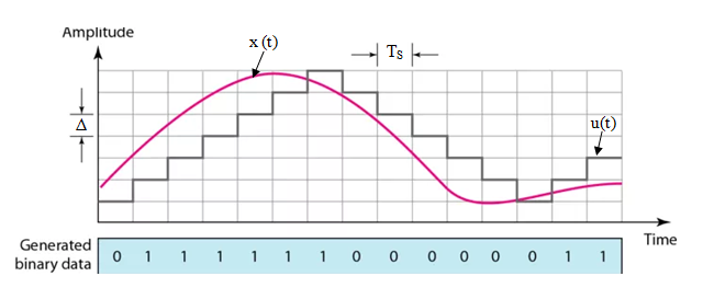
Fig.1. Delta Modulation Waveform
Mathematical Expressions
The error between the sampled value of x(t) and last approximated sample is given as:
![]()
Where e( nTs) = error at present sample
x(nTs) = sampled signal of x(t)
![]()
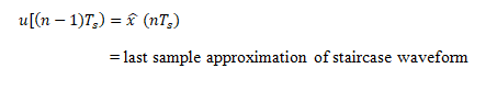
If we assume u(nTs) as the present sample approximation of staircase output, then
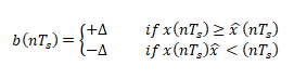
Let us define a quantity b( nTs) in such a way that,
![]()
This means that depending on the sign of error e( nTs) , the sign of step size Δ is decided. In other words we can write
Also if b (nTs) =+Δ then a binary ‘1’ is transmitted
and if b (nTs) =-Δ then a binary ‘0’ is transmitted
Here Ts = sampling interval.
Transmitter
Fig. 2 (a) shows the transmitter . It is also known as Delta modulator.
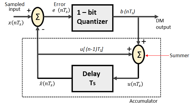
Fig.2 (a) Delta Modulation Transmitter
It consists of a 1-bit quantizer and a delay circuit along with two summer circuits.
The summer in the accumulator adds quantizer output (±Δ) with the previous sample approximation . This gives present sample approximation. i.e.,

The previous sample approximation u[(n-1)Ts ] is restored by delaying one sample period Ts .
The samples input signal x(nTs ) and staircase approximated signal xˆ(nTs ) are subtracted to get error signal e(nTs ).
Thus, depending on the sign of e(nTs ), one bit quantizer generates an output of +Δ or -Δ .
If the step size is +Δ, then binary ‘1’ is transmitted and if it is -Δ, then binary ‘0’ is transmitted .
Receiver
At the receiver end also known as delta demodulator, as shown in fig.2 (b) , it comprises of a low pass filter(LPF), a summer, and a delay circuit. The predictor circuit is eliminated here and hence no assumed input is given to the demodulator.
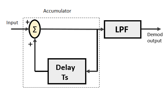
Fig.2 (b) Delta Modulation Receiver
The accumulator generates the staircase approximated signal output and is delayed by one sampling period Ts.
It is then added to the input signal.
If the input is binary ‘1’ then it adds +Δ step to the previous output (which is delayed).
If the input is binary ‘0’ then one step ‘Δ’ is subtracted from the delayed signal.
Also, the low pass filter smoothens the staircase signal to reconstruct the original message signal x(t) .