Explain Generation and Detection of PPM Signal
Last Updated on June 26, 2020 by Sasmita
Pulse Position Modulation (PPM)
In PPM, the amplitude and width of the pulses is kept constant but the position of each pulse is varied in accordance with the amplitudes of the sampled values of the modulating signal.
The position of the pulses is changed with respect to the position of reference pulses.
The PPM pulses can be derived from the PWM pulses as shown in fig.1.
Here, it may be noted that with increase in the modulating voltage the PPM pulses shift further with respect to reference.

Fig.1 : PPM pulses generated from PWM signal
The vertical dotted lines drawn in fig.1 are treated as reference lines to measure the shift in position of PPM pulses.
The PPM pulses marked 1, 2 and 3 in fig.1 go away from their respective reference lines. This is corresponding to increase in the modulating signal amplitude.
Then, as the modulating voltage decreases, the PPM pulses 4, 5, 6, 7 come progressively closer to their respective reference lines.
Generation of PPM Signal
The PPM signal can be generated from PWM signal as shown in fig.2 (a).
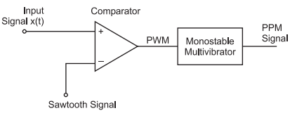
Fig.2 : Generation of PPM signal
The PWM pulses obtained at the comparator output are applied to a monostable multivibrator. The monostable is negative edge triggered.
Hence, corresponding to each trailing edge of PWM signal, the monostable output goes high.
It remains high for a fixed time decided by its own RC components.
Thus, as the trailing edges of the PWM signal keep shifting in proportion with the modulating signal x(t), the PPM pulses also keep shifting, as shown in fig.3.

Fig.3
Demodulation of PPM Signal
The PPM demodulator block diagram has been shown in fig.4 .

Fig.4
The operation of the demodulator circuit may be explained as under:
- The noise corrupted PPM waveform is received by the PPM demodulator circuit.
- The pulse generator develops a pulsed waveform at its output of fixed duration and applies these pulses to the reset pin (R) of a SR flip-flop.
- A fixed period reference pulse is generated from the incoming PPM waveform and the SR flip-flop is set by the reference pulses.
- Due to the set and reset signals applied to the flip-flop, we get a PWM signal at its output.
- The PWM signal can be demodulated using the PWM demodulator.