Explain the Direct Method for the Generation of FM Wave
Last Updated on May 21, 2025 by Sasmita
Frequency Modulation (FM) is a method of encoding information in a carrier wave by varying its frequency in accordance with the instantaneous amplitude of the modulating signal. FM is widely used in radio broadcasting, telemetry, radar, and two-way radio systems due to its superior noise immunity and improved signal quality over amplitude modulation (AM).
FM Generation
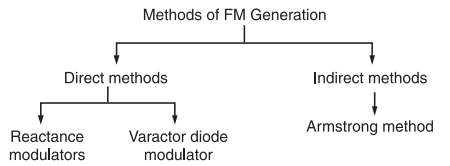
The FM modulator circuits used for generating FM signals can be divided into two categories such as:
(i) The direct method or parameter variation method
(ii) The Indirect method or the Armstrong method
The classification of FM generation methods is shown below :
The Direct Method or Parameter Variation Method
In direct method or parameter variation method, the baseband or modulating signal directly modulates the carrier.
The carrier signal is generated with the help of an oscillator circuit.
This oscillator circuit uses a parallel tuned L-C circuit.
Thus the frequency of oscillation of the carrier generation is governed by the expression:
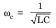
Now, we can make the carrier frequency ωc to vary in accordance with the baseband or modulating signal x(t) if L or C is varied according to x(t).
An oscillator circuit whose frequency is controlled by a modulating voltage is called voltage controlled oscillator (VCO).
The frequency of VCO is varied according to the modulating signal simply by putting a shunt voltage variable capacitor with its tuned circuit.
This voltage variable capacitor is called varactor or varicap.
This type of property is exhibited by reverse biased semiconductor diodes.Also the capacitance of bipolar junction transistors (BJT) and field-effect transistors (FET) is varied by the Miller-effect. This miller capacitance may be utilized for frequency modulation. In addition to this, the electron tubes may also provide variable reactance (either it is inductive or capacitive) which is proportional to modulating or baseband signal. This type of tubes are called reactance tubes and may be used for FM generation.
The inductance L of the tuned circuit may also be varied in accordance with the baseband or modulating signal x(t).
The FM circuit using such inductors is called saturable reactor modulator.
Frequency modulation can also be achieved from voltage controlled devices such as PIN diode, Klystron oscillators and multivibrators.
Reactance Modulator
In direct FM generation, the instantaneous frequency of the carrier is changed directly in proportion with the message signal.
For this, a device called voltage controlled oscillator (VCO) is used.
A VCO can be implemented by using a sinusoidal oscillator with a tuned circuit having a high value of Q.
The frequency of this oscillator is changed by changing the reactive components involved in the tuned circuit. If L or C of a tuned circuit of an oscillator is changed in accordance with the amplitude of modulating signal then FM can be obtained across the tuned circuit as shown in figure 1 below.
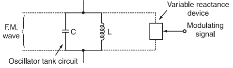
Fig.1 Principle of Reactance Modulator
A two or three terminal device is placed across the tuned circuit. The reactance of the device is varied proportional to modulating signal voltage. This will vary the frequency of the oscillator to produce FM. The devices used are FET, transistor or varactor diode.
An example of direct FM is shown in figure 1 which uses a Hartley oscillator along with a varactor diode.
The varactor diode is reverse biased. Its capacitance is dependent on the reverse voltage applied across it. This capacitance is shown by the capacitor C(t) in figure 2.
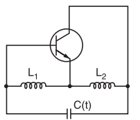
Fig.2 : Hartley Oscillator
Frequency of oscillations of the Hartley oscillator shown in figure 2 is given by :
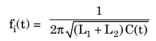
…………..(1)
where C(t) = C + Cvarector
This means that C(t) is the effective capacitance of the fixed tuned circuit capacitance C and the varactor diode capacitance Cvarector.
Let the relation between the modulating voltage x(t) = 0 and the capacitance C(t) be represented as under:
![]()
where C = total capacitance when x(t)
kc is the sensitivity of the varactor capacitance to change in voltage
Substituting expression for C(t) in equation(1) , we get
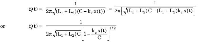
But, let
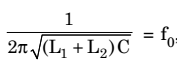
which is the oscillator frequency in absence of the modulating signal [x(t) = 0]. Therefore, we have,
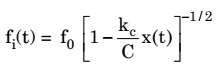
……………… (2)
If the maximum change in the capacitance corresponding to the modulating wave is assumed to be small as compared to the unmodulated capacitance C then equation (2) for fi (t) can be approximated as under:
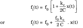
Now, let us define
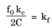
Therefore, we have
![]()
where kf is called as the frequency sensitivity of the modulator.
Varactor Diode Modulator
The varactor diode FM modulator has been shown below in figure 3.

Fig.3 : Varactor Diode Modulator
A varactor diode is a semiconductor diode whose junction capacitance varies linearly with the applied bias andThe varactor diode must be reverse biased.
Working Operation
The varactor diode is reverse biased by the negative dc source –Vb.
The modulating AF voltage appears in series with the negative supply voltage. Hence, the voltage applied across the varactor diode varies in proportion with the modulating voltage.
This will vary the junction capacitance of the varactor diode.
The varactor diode appears in parallel with the oscillator tuned circuit.
Hence the oscillator frequency will change with change in varactor dioide capacitance and FM wave is produced.
The RFC will connect the dc and modulating signal to the varactor diode but it offers a very high impedance at high oscillator frequency. Therefore, the oscillator circuit is isolated from the dc bias and modulating signal.