Explain the Generation of AM Waves using Square Law Modulator and Switching Modulator
Last Updated on January 9, 2020 by Sasmita
Generation of AM Waves
The circuit that generates the AM waves is called as amplitude modulator and in this post we will discuss two such modulator circuits namely :
- Square Law Modulator
- Switching Modulator
Both of these circuits use a non-linear elements such as a diode for their implementation . Both these modulators are low power modulator circuits .
Square Law Modulator
Generation of AM Waves using the square law modulator could be understood in a better way by observing the square law modulator circuit shown in fig.1 .
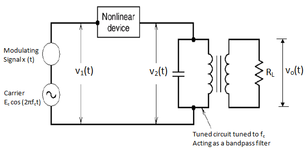
Fig 1
Please subscribe to Electronics Post Channel if you like my tutorials.
It consists of the following :
- A non-linear device
- A bandpass filter
- A carrier source and modulating signal
The modulating signal and carrier are connected in series with each other and their sum V1(t) is applied at the input of the non-linear device, such as diode, transistor etc.
Thus,
![]() …………………………(1)
…………………………(1)
The input output relation for non-linear device is as under :
![]() …………………………….(2)
…………………………….(2)
where a and b are constants.
Now, substituting the expression (1) in (2), we get
![]()
Or,
![]()
Or,
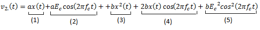
The five terms in the expression for V2(t) are as under :
Term 1: ax(t) : Modulating Signal
Term 2 : a Ec cos (2π fct ) : Carrier Signal
Term 3 : b x2 (t) : Squared modulating Signal
Term 4 : 2 b x(t) cos ( 2π fct ) : AM wave with only sidebands
Term 5 : b Ec2 cos2 (2π fct ) : Squared Carrier
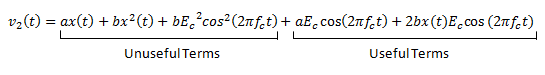
Out of these five terms, terms 2 and 4 are useful whereas the remaining terms are not useful .
Let us club terms 2, 4 and 1, 3, 5 as follows to get ,
The LC tuned circuit acts as a bandpass filter . Its frequency responce is shown in fig 2 which shows that the circuit is tuned to frequency fc and its bandwidth is equal to 2fm . This bandpass filter eliminates the unuseful terms from the equation of v2(t) .
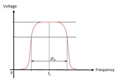
Fig 2
Hence the output voltage vo(t) contains only the useful terms .
![]()
Or,
![]()
Therefore ,
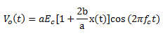 ………………………….(3)
Comparing this with the expression for standard AM wave i.e.
![]() ,
,
We find that the expression for Vo(t) of equation (3) represents an AM wave with m = (2b/a) .
Hence, the square law modulator produces an AM wave .
Switching Modulator
Generation of AM Waves using the switching modulator could be understood in a better way by observing the switching modulator diagram. The switching modulator using a diode has been shown in fig 3(a) .
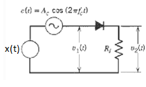
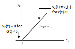
Fig 3 (a) Fig 3(b)
This diode is assumed to be operating as a switch .
The modulating signal x(t) and the sinusoidal carrier signal c(t) are connected in series with each other. Therefore, the input voltage to the diode is given by :
![]()
The amplitude of carrier is much larger than that of x(t) and c(t) decides the status of the diode (ON or OFF ) .
Working Operation and Analysis
Let us assume that the diode acts as an ideal switch . Hence, it acts as a closed switch when it is forward biased in the positive half cycle of the carrier and offers zero impedance . Whereas it acts as an open switch when it is reverse biased in the negative half cycle of the carrier and offers an infinite impedance .
Therefore, the output voltage v2(t) = v1(t) in the positive half cycle of c(t) and v2(t) = 0 in the negative half cycle of c(t) .
Hence , v2(t) = v1(t) for c(t) > 0
v2(t) = 0 for c(t) < 0
In other words , the load voltage v2(t) varies periodically between the values v1(t) and zero at the rate equal to carrier frequency fc .
We can express v2(t) mathematically as under :
![]() …………………………(4)
…………………………(4)
where, gp(t) is a periodic pulse train of duty cycle equal to one half cycle period i.e. T0 /2 (where T0 = 1/fc) .

Fig.4
Let us express gp(t) with the help of Fourier series as under :
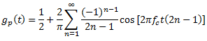 …………………………….(5)
![]() ……………………………(6)
……………………………(6)
Substituting gp(t) into equation (4), we get
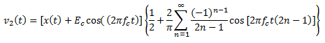
Therefore,
![]() ………………………..(7)
………………………..(7)
The odd harmonics in this expression are unwanted, and therefore, are assumed to be eliminated .
Hence,
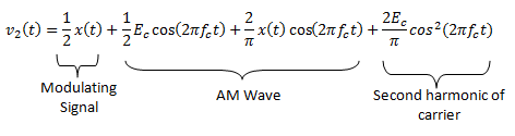
In this expression, the first and the fourth terms are unwanted terms whereas the second and third terms together represents the AM wave .
Clubing the second and third terms together , we obtain
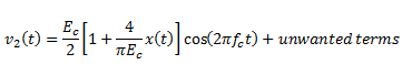
This is the required expression for the AM wave with m=[4/πEc] . The unwanted terms can be eliminated using a band-pass filter (BPF) .