Explain The Generation of DSB-SC Signal with Balanced Modulator Using Diodes
Last Updated on December 8, 2015 by Sasmita
Balanced Modulator Using Diodes
We already know that a non-linear resistance or non-linear device may be used to produce Amplitude Modulation i.e. one carrier and two sidebands .
However, a DSB-SC signal contains only two sidebands . Thus, if two non-linear devices such as diodes, transistors etc. are connected in a balanced mode so that they suppress the carriers of each other, then only sidebands are left and a DSB-SC signal is generated .
Therefore, a balanced modulator may be defined as a circuit in which two non-linear devices are connected in a balanced mode to produce a DSB-SC signal .
In this article, we shall discuss a balanced modulator circuit using diodes .
Fig.1 shows the balanced modulator using diodes as non-linear device .
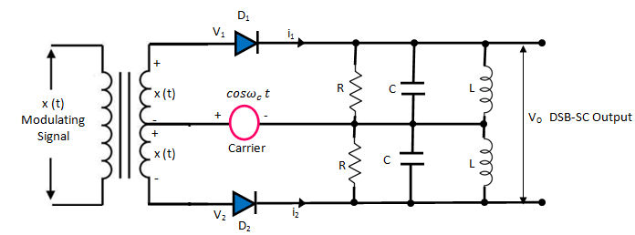
Fig 1
The modulating signal x(t) is applied equally with 180o phase reversal at the inputs of both the diodes through the input center tapped transformer .
The carrier is applied to the center tap of the secondary .
Hence, input voltage to D1 is given by :
![]() ……..(1)
……..(1)
And the input voltage to D2 is given by :
![]() ……….(2)
……….(2)
The parallel RLC circuits on the output side form the band pass filters .
Analysis
The diode current i1 and i2 are given by :
![]()
![]()
![]() ………………(3)
………………(3)
Similarly,
![]()
![]()
![]() …………(4)
…………(4)
The output voltage is given by :
![]()
Substituting the expression for i1 and i2 from equations (3) and (4), we get
![]()
Or,
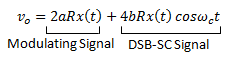
Hence, the output voltage contains a modulating signal term and the DSB-SC signal .
The modulating signal term is eliminated and the second term is allowed to pass through to the output by the LC band pass filter section .
Therefore, final output = 4 b R x(t) cos ωct
= K x(t) cos ωct
Thus, the diode balanced modulator produces the DSB-SC signal at its output .