Explain The Logic EX-NOR Gate (Exclusive-NOR Gate) and Its Operation with Truth Table
Last Updated on November 10, 2015 by Sasmita
EX-NOR Gate
The exclusive-NOR circuit, abbreviated as EX-NOR, operates just opposite to the EX-OR circuit. The symbol of an EX-NOR gate is given in fig.1 .
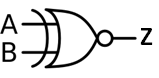
Fig 1
Basically the “Exclusive-NOR ” gate is a combination of the Exclusive-OR gate and the NOT gate.
This gate has high output if and only if its both inputs are same (either 0 or 1) and its output is low if and only if inputs are different. The output equation of this gate is given as :
![]()
It is obvious that the output of the EX-NOR circuit is the exact inverse of the output of the EX-OR circuit.
The EX-NOR gate is also called a coincidence gate, because its output is a 1 only when its input coincide (either 0,0 or 1,1). It can be used as an equality detector because its output is a 1 only when its inputs are equal.
Truth Table of EX-NOR Gate
The truth table for two input EX-NOR gate is given below in table 1.
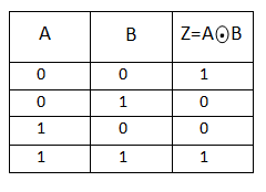
Table 1
When both A and B are the SAME the EX-NOR gate will give an output at Z.
In general, an Exclusive-NOR gate will give an output value of logic “1” ONLY when there are an EVEN number of 1’s on the inputs to the gate (the inverse of the Ex-ORgate) except when all its inputs are “LOW”.
Ex-NOR Gate Equivalent Circuit
The Ex-NOR function is a combination of different basic logic gates Ex-OR and a NOT gate, and by using the 2-input truth table above, we can expand the Ex-NOR function to:
![]()
which means we can realise this new expression using the following individual gates.
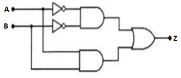
Fig 2
Ex-NOR Function Realisation using NAND gates
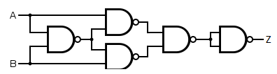
Fig 3
Ex-NOR Function Realisation using NOR gates
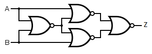
Fig 4
Standard Package
Fig 5 shows the pinout diagram of an IC 74266, a TTL quad-2 input EX-NOR gate.
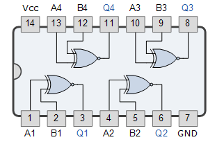
Fig 5
It contains four 2-input EX-NOR gates in a 14-pin DIP.
Pulsed Operation of EX-NOR Gate
The pulsed operation of an EX-NOR gate is illustrated in fig 6 .
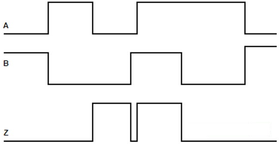
Fig 6
Initially when one of the two inputs of the EX-NOR gate is low, the output is at low level. When both the input changes to low level, the EX-NOR output will rise to HIGH level and again when one of the inputs comes to low level, the output also comes to low level.