Explain Various Types of Low Pass Filters
Last Updated on October 14, 2015 by Sasmita
Low Pass Filters
The simplest approach to build a filter is with passive components such as resistors, capacitors, and inductors. In RF range it works quite well, however, with lower frequencies, inductors create problems. Since for lower frequencies the inductance is to be increased which needs more turns of wire. It adds to the series resistance which degrades the inductor’s performance.
AF inductors are physically larger and heavier, and therefore expensive.
Low pass filters are of many types such as R-C,R-L, inverted L-type, T-type and π-type.
Low Pass R-C Filter Circuit
A simple R-C Low Pass Filter or LPF, can be easily made by connecting together in series a single resistor with a single capacitor as shown below.
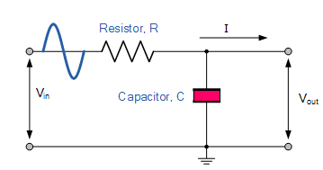
In this circuit, the input signal ( Vin ) is applied to the series combination of both the resistor and capacitor , and the output signal ( Vout ) is taken across the capacitor only.
This type of filter is known generally as a “first-order filter” or “one-pole filter”.
Why first-order or single-pole?
Because it has only “one” reactive component, the capacitor, in the circuit.
As we already know that, the reactance of a capacitor varies inversely with frequency, while the value of the resistor remains constant as the frequency changes.
At low frequencies the capacitive reactance, ( Xc ) of the capacitor will be very large compared to the resistive value of the resistor, R. This means that the voltage potential, Vc across the capacitor will be much larger than the voltage drop, Vr developed across the resistor.
At high frequencies the reverse is true with Vc being small and Vr being large due to the change in the capacitive reactance value.
At zero frequency, the capacitor acts as an open circuit and output is same as input.
However, with increase in frequency, the capacitive reactance decreases and so the output voltage. At infinity frequency, the capacitive reactance of the circuit will be zero and therefore, output voltage will also be zero.
Since it passes low frequency signals and blocks the high frequency signals, it is called as low pass filter.
The capacitive reactance of the capacitor in Ohms is given as :
![]()
For a series circuit consisting of a single resistor in series with a single capacitor, the circuit impedance Z is calculated as:
![]()
Hence the output voltage across the capacitor is given as :
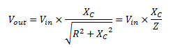
Using this formula we can calculate the output voltage at any frequency.
Frequency Response of Low pass Filter
We have already discussed above that , as the frequency applied to the RC network increases , the voltage dropped across the capacitor and therefore the output voltage ( Vout ) from the circuit decreases .
By plotting the output voltage against different values of input frequency, the Frequency Response Curve or Bode Plot function of the low pass filter circuit can be found, as shown below.
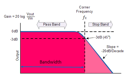
As we can see from the above fig., the frequency response of the filter is nearly flat for low frequencies and all of the input signal is passed directly to the output, resulting in a gain of nearly 1, called unity, until it reaches its Cut-off Frequency point ( ƒc ).
This is because the reactance of the capacitor is high at low frequencies and blocks any current flow through the capacitor.
After this cut-off frequency point the response of the circuit decreases to zero at a slope of -20dB/ Decade or (-6dB/Octave) roll-off. Note that the angle of the slope, this -20dB/ Decade roll-off will always be the same for any RC combination.
Any high frequency signals above this cutoff frequency, applied to the low pass filter circuit will become greatly attenuated, that is they rapidly decrease. This happens because at very high frequencies the reactance of the capacitor becomes so low that it gives the effect of a short circuit condition on the output terminals resulting in zero output.
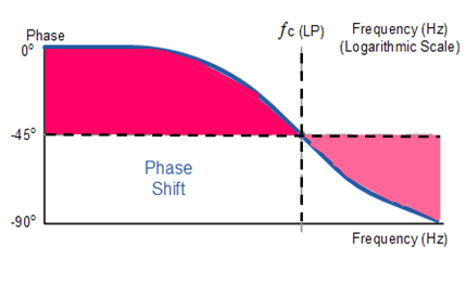
The Cut-off frequency is defined as being the frequency point where the capacitive reactance and resistance are equal, i.e. R = Xc . At this cut off frequency the phase angle is 45o and the output power is half of the input power. The output voltage is 0.707 times the maximum value of voltage Vmax .
This cut off frequency fc is given as :
![]()
Low Pass R-L Filter Circuit
The circuit of a low pass R-L circuit is shown in fig. below.
In this circuit the output voltage is taken across the resistance R.
Since the reactance offered by the inductor L , increases with the increase in frequency, so it allows the frequencies up to cut off frequency fc to pass through the coil without much opposition but offers high reactance to frequencies above the cut off frequency.
The output developed across resistor R is given by the following equation :

The cut off frequency fc is given as:

Cutoff frequency occurs when output voltage Vmax = 0.707 times input voltage, R = XL , VR = VL and impedance phase angle is 45o .
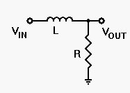
Inverted L – type Filter Circuit
This filter circuit employs a choke and a capacitor. The circuit of an inverted L-type filter circuit is shown in fig. below.

Since the choke offers high reactance to high frequencies, it blocks them and the capacitor C short them to ground as it offers negligible reactance to the high frequencies.
Thus only low frequencies below cutoff frequency fc are allowed to pass through without significant attenuation.
In this filter, the output is taken across the capacitor C.
T-type Filter Circuit
Such a filter circuit consists of a second choke connected on the output side in order to improve the filtering action.
Such a filter circuit is shown in fig. below.

π-type Filter Circuit
Such a filter circuit is shown in fig. below.
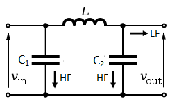
Here a second capacitor C2 is added in the circuit to improve the filtering action by grounding higher frequencies.
The inductor or choke is always connected in series between the input and output and the capacitors are grounded in parallel.
The output voltage is taken across the capacitor C2 .