Full Adder
Last Updated on September 27, 2015 by Sasmita
Full Adder
The main difference between the Full Adder and the Half Adder is that a full adder has three inputs. The same two single bit data inputs A and B as before plus an additional Carry-in (C-in) input to receive the carry from a previous stage as shown in the full adder block diagram below.
Full Adder Block Diagram

Fig.1
A full adder is a logical circuit that performs an addition operation on three binary digits and just like the half adder, it also generates a carry out to the next addition column.
Here a Carry-in is a possible carry from a less significant digit, while a Carry-out represents a carry to a more significant digit.
In many ways, the full adder can be thought of as two half adders connected together, with the first half adder passing its carry to the second half adder as shown below in fig.4.
Full Adder Logic Diagram
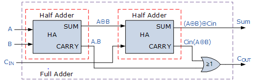
Fig.2
As the full adder circuit above is basically two half adders connected together, the truth table for the full adder includes an additional column to take into account the Carry-in, CIN input as well as the summed output, S and the Carry-out, COUT bit.
Full Adder Truth Table with Carry

The Boolean expression for a full adder is as follows:
For the SUM(S) bit:
![]()
For the CARRY-OUT (COUT) bit:
![]()
An n-bit Binary Adder
We have seen above that single 1-bit binary adders can be constructed from basic logic gates. So to add together two n-bit numbers, n number of 1-bit full adders needs to be connected or “cascaded” together to produce a Ripple Carry Adder.
A ripple carry adder is simply n, 1-bit full adders cascaded together with each full adder representing a single weighted column in a long binary addition. It is called a ripple carry adder because the carry signals produce a ripple effect through the binary adder from right to left, (LSB to MSB).
For example, suppose we want to “add” together two 4-bit numbers, the two outputs of the first full adder will provide the first place digit sum (S) of the addition plus a carry-out bit that acts as the carry-in digit of the next binary adder.
The second binary adder in the chain also produces a summed output (the 2nd bit) plus another carry-out bit and we can keep adding more full adders to the combination to add larger numbers, linking the carry bit output from the first full binary adder to the next full adder, and so forth.
An example of a 4-bit adder is given below.
A 4-bit Ripple Carry Adder

Fig.3
One main disadvantage of cascading together 1-bit binary adders to add large binary numbers is that if inputs A and B change, the sum at its output will not be valid until any carry-input has “rippled” through every full adder in the chain because the MSB (most significant bit) of the sum has to wait for any changes from the carry input of the LSB (less significant bit). Consequently, there will be a finite delay before the output of the adder responds to any change in its inputs resulting in a accumulated delay.
When the size of the bits being added is not too large for example, 4 or 8 bits, or the summing speed of the adder is not important, this delay may not be important. However, when the size of the bits is larger for example 32 or 64 bits used in multi-bit adders, or summation is required at a very high clock speed, this delay may become prohibitively large with the addition processes not being completed correctly within one clock cycle.
This unwanted delay time is called Propagation delay. Also another problem called “overflow” occurs when an n-bit adder adds two parallel numbers together whose sum is greater than or equal to 2.
One solution is to generate the carry-input signals directly from the A and B inputs rather than using the ripple arrangement above. This then produces another type of binary adder circuit called a Carry Look Ahead Binary Adder where the speed of the parallel adder can be greatly improved using carry-look ahead logic.
The advantage of carry look ahead adders is that the length of time a carry look ahead adder needs in order to produce the correct SUM is independent of the number of data bits used in the operation, unlike the cycle time a parallel ripple adder needs to complete the SUM which is a function of the total number of bits in the addend.
4-bit full adder circuits with carry look ahead features are available as standard IC packages in the form of the TTL 4-bit binary adder 74LS83 or the 74LS283 and the CMOS 4008 which can add together two 4-bit binary numbers and generate a SUM and a CARRY output as shown below in fig.6.
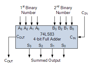
Fig.4