How to test a Diode with a Multimeter
Last Updated on November 27, 2018 by Sasmita
How to test a Diode with a Multimeter
Before going for the assembly of the basic electronic components in any particular circuit, it is always advisable to test the components about their working condition or functioning, to avoid the undesired outcome.
So we need to conduct some testing procedures for the main components in the circuit to know their proper working. So, let us look on how to test diodes with a multimeter.
How to test a diode
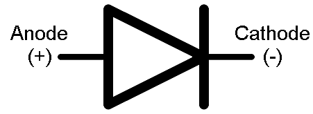
The diode is a two terminal semiconductor device which allows the current flow only in one direction. These are found in many applications such as rectifiers, clampers, clippers and so on.
The testing of the diode is done to know its proper working conditions in forward and reverse bias modes.
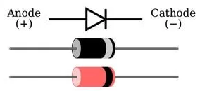
Before testing of the diode, the terminals of the diode must be identified. That means which terminal is anode and which one is cathode. Most of the PN diodes have the silver-band on its body and this white-band side terminal is the cathode. And the remaining one is anode. Some diodes may have a different color band, but the color band side terminal is the cathode.
The basic diode test is very simple to perform. Just two tests are needed with the multimeter to ensure that the diode works satisfactorily.
The method of testing a diode with an analog meter is quite straightforward.
Testing of a Diode using Analog Multimeter
Step by Step Instructions:
- Set the multimeter selector switch in low resistance value.
- Connect the negative terminal of the diode to the negative terminal of the multimeter.
- Connect the positive terminal of the diode to the positive terminal of the multimeter.
- If the meter indicates a low resistance value, then it says that the diode is healthy.
- Now put the selector in high resistance position and reverse the terminals of the meter by connecting positive terminal to the cathode and negative terminal to anode. In this case, the diode is said to be in reverse bias.
- If the meter indicates OL or a very high resistance, then it refers to the perfect condition of the diode.
- If the meter fails to show above readings, then the diode is said to be defective or bad.

Testing of a Diode using Digital Multimeter
The diode testing using a digital multimeter (DMM) can be carried in two ways as there are two modes available in DMM to check the diodes such as diode mode and ohmmeter mode.
Diode Mode Testing
Step by Step Instructions:
- Identify the diode terminals (anode and cathode).
- Keep the digital multimeter (DMM) in diode checking mode by rotating the central knob to the place where the diode symbol is indicated. In this mode multimeter is capable to supply a current of 2mA approximately between the test leads.
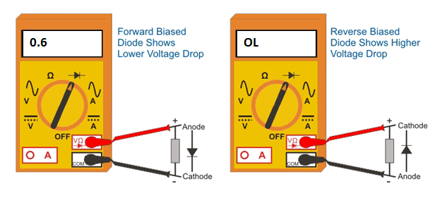
- Connect the red probe to the anode and black probe to the cathode. This means diode is forward-biased.
- Observe the reading on the meter display. If the displayed voltage value is in between 0.6 to 0.7 (since it is silicon diode) then the diode is healthy and perfect. For germanium diodes this value is in between 0.25 to 0.3.
- Now reverse the terminals of the meter that means connect the red probe to cathode and black to anode. This is the reverse biased condition of the diode where no current flows through it. Hence the meter should read OL (which is equivalent to open circuit) if the diode is healthy.
- If the meter shows irrelevant values to the above two conditions, then the diode is defective.
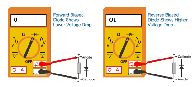
The diode defect can be either open or short. Open diode means diode behaves as an open switch in both reverse and forward-biased conditions. So, no current flows through the diode. Therefore, the meter will indicate OL in both reverse and forward-biased conditions.
Shorted diode means diode behaves as a closed switch so the current flows through it and the voltage drop across the diode will be zero. Therefore, the multimeter will indicate zero voltage value, but in some cases it will display a very little voltage as the voltage drop across the diode.
Ohmmeter Mode Testing
Step by Step Instructions:
- Identify the terminals anode and cathode of the diode.
- Keep the digital multimeter (DMM) in resistance or ohmmeter mode by rotating the central knob or selector to the place where ohm symbol or resistor values are indicated. Keep the selector in low resistance (may be 1K ohm) mode for forward-bias.
- Connect the red probe to the anode and black probe to the cathode. This means diode is forward-biased. When the diode is forward-biased, the resistance of the diode is so small.
- If the meter displays a moderately low value on the meter display, which may be a few tens to few hundred ohms, then the diode is good and healthy.
- Now reverse the terminals of the multimeter such that anode is connected to black probe and cathode to red probe. So the diode is reverse biased.
- Keep the selector in high resistance mode (may be 100K ohm) for the reverse bias testing procedure.
- If the meter shows a very high resistance value or OL on meter display, then the diode is good and functions properly. Since in reverse biased condition diode offers a very high resistance.
From the above it is clear that for proper working of the diode, DMM should read a very low resistance in the forward-biased condition and a very high resistance or OL in reverse-biased condition.
If the meter indicates a very high resistance or OL in both forward and reverse-biased conditions, then the diode is said to be opened. In other hand, if the meter reads a very low resistance in both directions, then the diode is said to be shorted.