Introduction to Double Sideband Suppressed Carrier (DSB-SC) System . Explain The Generation of DSB-SC Signal
Last Updated on December 3, 2015 by Sasmita
Double Sideband Suppressed Carrier (DSB-SC) System
Definition and Mathematical Expression
The equation of AM wave in its simplest form i.e. single tone modulation, is expressed as :
![]()
From this equation, it is obvious that the carrier component in AM wave remains constant in amplitude and frequency . This means that the carrier of amplitude modulated wave does not convey any information .
In power calculation of AM signal, it has been observed that for single-tone sinusoidal modulation, the ratio of the total power to the carrier power is :

where ma is the modulating index
Thus, for 100% modulation about 67% of the total power is required for transmitting the carrier which does not contain any information .
Hence, if the carrier is supressed, only the sidebands remain and in this way a saving of two-third power may be achieved at 100% modulation .
The resulting signal obtained by supressing the carrier from the modulated wave is called Double sideband supressed carrier (DSB-SC) system .
Generation of DSB-SC Signal
A DSB-SC signal can be obtained by simply multiplying modulating signal x(t) with carrier signal cosωct . So we need to use a device called product modulator for the generation of DSB-SC waves .
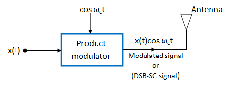
Fig 1
There are two forms of product modulators as under :
- Linear Modulator
- Non-linear Modulator
Linear Modulator for DSB-SC Generation
A linear modulator is a system whose gain or transfer function can be varied with time by applying a time varying signal at certain points .
The gain is proportional to signal f(t) .
G = K f(t)
Where G = gain
K = constant of proportionality
f(t) = gain varying signal
Let us consider fig.2 in which the carrier signal cosωct is applied at the input terminal and x(t) is applied as the gain varying signal .
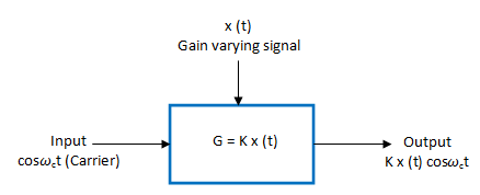
Fig 2 :Linear Modulator
The gain of the modulator is G = K x(t) .
Therefore, the output is given by :
![]()
Or,
![]()
This is a modulated signal (DSB-SC) .
AS an alternative we can use the carrier as gain varying signal and x(t) as the input signal as shown in fig 3 .
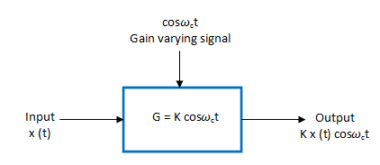
Fig 3: Another variation of Linear Modulator
The gain of the modulator is given by :
G = K cosωct
Therefore,
![]()
This is same as before .
Balanced Modulator (Suppression of Carrier )
The balanced modulators are used to suppress the unwanted carrier in AM wave .
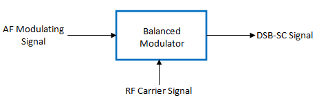
Fig.4 : Block Diagram of Balanced Modulator
The carrier and modulating signals are applied to the inputs of the balanced modulator and we get the DSB signal with supressed carrier at the output of the balanced modulator . Hence, the output consists of the upper and lower sidebands only .
Principle of Operation
The principle of operation of a balanced modulator states that if two signals at different frequencies are passed through a non-linear resistance then at the output, we get an AM signal with suppressed carrier . The device having a non-linear resistance can be a diode or a JFET or even a bipolar transistor .
Types of Balanced Modulator
The suppression of carrier can be done using the following two balanced modulators :
- Using the diode ring modulator or lattice modulator
- Using the FET balanced modulator
Balanced Modulator using AM Modulator
The block diagram of a balanced modulator is shown in fig.5 .
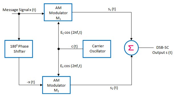
Fig 5 : Balance Modulator for DSB-SC genaration
It consists of two standard amplitude modulators arranged in the balanced configuration so as to suppress the carrier completely .
Working Operation and Analysis
The carrier signal c(t) is connected to both AM modulators M1 and M2 .
The message signal x(t) is applied as it is to M1 and its inverted version -x(t) is applied to M2.
At the outputs of modulators M1 and M2 , we get standard AM signals s1(t) and s2(t) as under :
output of M1 : s1(t) = Ec[1 + m x (t)] cos (2π fct)
output of M2 : s2(t) = Ec[1 – m x (t)] cos (2π fct)
These are then applied to a subtractor and the subtractor produces the desired DSB-SC signal as under :
Subtractor output = s1(t) – s2(t) = Ec[1 + m x (t)] cos (2π fct) – Ec[1 – m x (t)] cos (2π fct)
= Eccos (2π fct)[{1 + m x (t)}-{1 – m x (t)}]
= Eccos (2π fct)[1 + m x (t)- 1 + m x (t)]
= 2m Ecx (t)cos (2π fct)
The R.H.S. of this expression consists of product of x(t) and c(t) = Eccos (2π fct) .
Hence, it represents a DSB-SC signal .