PLL FM Demodulator (Phase Locked Loop FM Demodulator)
Last Updated on June 12, 2020 by Sasmita
PLL FM Demodulator
A Phase-Locked Loop (PLL) is basically a negative feedback system. It consists of three major components such as re multiplier, a loop filter and a voltage controlled oscillator (VCO) connected together in the form of a feedback loop.
A VCO is a sine wave generator whose frequency is determined by the voltage applied to it from an external source. It means that any frequency modulator can work as a VCO.
A phase-locked loop (PLL) is primarily used in tracking the phase and frequency of the carrier component of an incoming FM signal.
PLL is also useful for synchronous demodulation of AM-SC (i.e., Amplitude Modulation with Suppressed carrier) signals or signals with few cycles of pilot carrier.
Further, PLL is also useful for demodulating FM signals in presence of large noise and low signal power.
This means that, PLL is most suitable for use in space vehicle-to-earth data links or where the loss along the transmission line or path is quite large.
Recently, it has found application in commercial FM receivers.
The block diagram of a PLL is shown in fig.1 below.
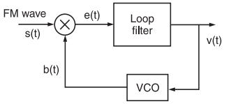
Fig.1: The block diagram of a Phase-Locked Loop (PLL)
Working Operation
The operation of a PLL is similar to any other feedback system where the feedback signal tends to follow the input signal.
If the signal fed back is not equal to the input signal, the error signal will change the value of the fed back signal until it is equal to the input signal.
The difference signal between s(t) and b(t) is called an error signal.
A PLL operates on a similar principle except for the fact that the quantity feedback is not the amplitude, but a generalized phase Φ(t).
The error signal or difference signal e(t) is utilized to adjust the VCO frequency in such a way that the instantaneous phase angle comes close to the angle of the incoming signal s(t).
At this point, the two signals s(t) and b(t) are synchronized and the PLL is locked to the incoming signal s(t).
Mathematical Explanation
Here, we have assumed that the VCO is adjusted initially so that when the control voltage comes to zero, the following two conditions are satisfied:
(i) The frequency of the VCO is precisely set at the unmodulated carrier frequency fc
(ii) The VCO output has a 90° phase-shift w.r.t. the unmodulated carrier wave.
Let the input signal applied to the PLL be an FM wave. It is defined as ,
![]()
………………..(1)
where A is the unmodulated carrier amplitude and ωc = 2πfc = Angular carrier frequency and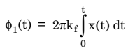
…………. (2)
where x(t) is the message or baseband signal or modulating signal
and kf = frequency sensitivity of frequency modulator.
Let the VCO output be defined by,
![]()
…………. (3)
where Av = Amplitude of VCO output when the control voltage applied to the VCO is denoted by v(t), then, we have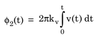
……………. (4)
Here, kv is the frequency sensitivity of VCO, measured in Hertz/volt.
It may be observed from equations (1) and (3) that the VCO output and the incoming signals are 90° out of phase, while the VCO frequency in absence of v(t) is precisely equal to the unmodulated frequency of the FM signal.
The incoming FM have s(t) and the VCO output b(t) are applied to a multiplier.
The output of the multiplier has the following components:
(i) A high frequency component represented by,
![]()
(ii) A low frequency component represented by,
![]()
where km = Multiplier Gain measured in per volt.
The high frequency component can be eliminated by using a filter. Hence, discarding the high frequency component, the effective input to the low pass filter (LPF) will be given by,
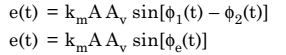
where Φe(t) is the phase error and is expressed as,
![]()
……………. (5)
This means that
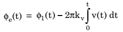
……………… (6)
The loop filter operates on error signal e(t) to produce the output v(t). It is given by,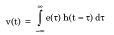
………………. (7)
where h(t) = Impulse response of the low-pass filter (LPF).
Using equations (5), (6) and (7), we get,
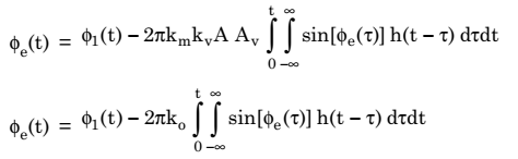
………………….. (8)
where ko = km kv A Av
Now, differentiating both sides of equation (8), we get,
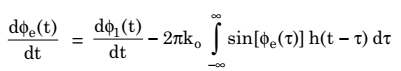
……………. (9)
Here, ko has the dimension of frequency. On the basis of equation (9), we can construct and equivalent model of PLL as shown in fig.2 below.
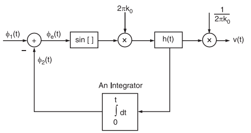
Fig.2 : A non-linear equivalent model of PLL
In this model, v(t) and e(t) are also included utiliZing the relationship between them as given in equations,
![]()
and
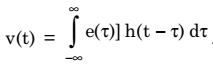
If we compare fig.1 and fig. 2, we can see that they are similar except for the fact that the multiplier in the equivalent model has been replaced by a subtractor and a sinusoidal non-linearity and the VCO by an integrator.
When the phase error Φe(t) is zero, then PLL is said to be phase-locked. When the phase error Φe(t) at all times is small compared to 1 radian, then we can approximate sin[Φe(t)] as Φe(t), i.e.,
![]()
It is almost accurate as long as Φe(t) is less than 0.5 radian. In this case, PLL is said to be Near-Lock Condition and the sinusoidal non-linearity can be discarded.
The linearized model of PLL is valid under above-mentioned condition as shown in fig.3.
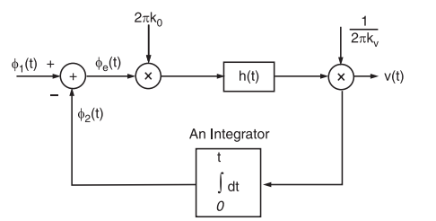
Fig.3 : Equivalent model of PLL
In this model, phase error Φe(t) is related to the input phase Φ1(t) by the Integro-differential equation. It is expressed as,
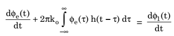
…………… (10)
Taking the Fourier transform of both sides of equation (10), we get,
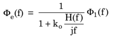
…………….. (11)
where Φe(f) and Φ1(f) are the Fourier transform of Φe(t) and Φ1(t), respectively and H(f) is the Fourier transform of impulse response h(t) and is known as transfer function of the loop filter.
The quantity ko(H(f)/ jf is called the open loop transfer function of the PLL.
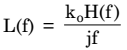
Substituting L(f) in the previous equation (10), we get,
![]()
Now, let us consider that for all values of frequency f inside the baseband signal, we make the magnitude of L(f) very large compared to unity. Thus, from equation (10) we get,
![]()
Under above-mentioned condition, the phase of the VCO becomes asymptotically equal to the phase of the incoming wave and the phase lock is thereby established.