Resistor Color Code
Resistor Color Code
In our previous post we saw that there are many different types of Resistor available that can be used in both electrical and electronic circuits.
The resistance value is a discrete value. For example, the values 1, 2.2, 4.7 and 10 are used in a typical situation.
Since the average resistor is too small to have the value printed on it, the resistance value is displayed using the color code ( the colored bars/the colored stripes ).
Resistor Color Coding
This is an international and universally accepted method, developed many years ago as a simple and quick way of identifying a resistors ohmic value no matter what its size or condition.
It consists of a set of individual colored rings or bands in spectral order representing each digit of the resistors value.
The resistor color code markings are always read one band at a time starting from the left to the right, with the larger width tolerance band oriented to the right side indicating its tolerance.
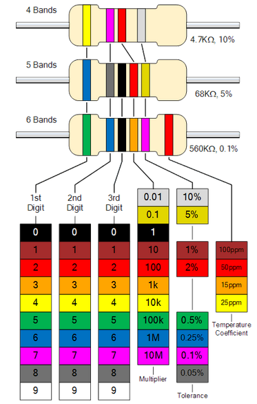
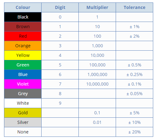
By matching the color of the first band with its associated number in the digit column of the color chart below the first digit is identified and this represents the first digit of the resistance value.
Again, by matching the color of the second band with its associated number in the digit column of the color chart we get the second digit of the resistance value and so on.
Standard Resistor Color Code Chart

Resistor Color Code Table

Calculating Resistor Values
In order to calculate the correct value of resistance, the following method is used in a color code system :
The left-hand or the most significant colored band is the band which is nearest to a connecting lead with the color coded bands being read from left-to-right as follows;
Digit, Digit, Multiplier = Color, Color x 10 color in Ohm’s (Ω’s)
Example 1 :
Let us take a resistor which has the following colored markings;

Resistance = Yellow, Violet, Black, Red = 4, 7 ,0,2 = 4 70 x 102 = 4700oΩ or 47 k Ω
The fifth bands is used to determine the percentage tolerance of the resistor.
Hence, Tolerance (Brown)= ±1%
Tolerance of the resistor is also an important property to consider.A 100 Ω resistor with 10% tolerance, means that its value can be any fixed value between 90 to 110 ohms.
Hence the resistor tolerance can be defined as a measure of the resistors variation from the specified resistive value and is a consequence of the manufacturing process and is expressed as a percentage of its “nominal” or preferred value.
If resistor has no fourth tolerance band then the default tolerance would be at 20%.
Example 2:

Resistance = Brown, Black, Orange = 1, 0 ,3 = 10 x 103 = 10 kΩ
Tolerance(Gold) = ±5%
