Solid State Relay (SSR): Working, Types, and Applications
Introduction
A Solid State Relay (SSR) is an electronic switching device that performs the same function as an electromechanical relay (EMR) but without moving parts. Instead of mechanical contacts, it uses semiconductor devices such as thyristors, triacs, or transistors to switch electrical loads. SSRs offer advantages like high reliability, fast response, and long operational life, making them widely used in industrial, commercial, and household applications.
Construction of Solid State Relay
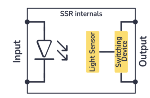
An SSR typically consists of three main sections:
-
Input Circuit (Control Side):
-
Accepts the control signal (DC or AC).
-
Uses an opto-isolator (LED and photodiode/phototransistor) to provide electrical isolation between the input and output.
-
-
Isolation Circuit:
-
Ensures that the control and load circuits are electrically separated.
-
Usually implemented using opto-couplers to enhance safety and prevent interference.
-
-
Output Circuit (Load Side):
-
Consists of semiconductor switching devices such as triacs, thyristors, or MOSFETs.
-
Responsible for controlling the load current.
-
Working Principle of SSR
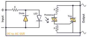
When a control voltage is applied to the input terminals:
-
The LED inside the opto-isolator emits light.
-
The photodetector or phototransistor detects this light and activates the output circuit.
-
Semiconductor switching devices (e.g., triac, MOSFET) turn ON, allowing current to flow through the load.
-
When the control signal is removed, the semiconductor device turns OFF, stopping the current flow.
Since there are no moving contacts, the switching is silent, fast, and wear-free.
Types of Solid State Relays
-
AC SSRs:
-
Control AC loads.
-
Often use triacs or thyristors for switching.
-
Example: Motor control, heating systems.
-
-
DC SSRs:
-
Designed to control DC loads.
-
Typically use MOSFETs or IGBTs.
-
Example: Battery systems, automotive electronics.
-
-
Zero-Crossing SSRs:
-
Turn ON when the AC voltage waveform crosses zero.
-
Reduce electrical noise and surges.
-
Ideal for resistive loads like heaters.
-
-
Random Turn-On SSRs:
-
Can turn ON at any point of the AC waveform.
-
Suitable for inductive loads like motors.
-
Advantages of Solid State Relays
-
Longer Life: No mechanical wear and tear.
-
Silent Operation: No clicking sound during switching.
-
Fast Switching Speed: Microsecond response time.
-
Electrical Isolation: High safety due to opto-isolation.
-
Resistance to Shock and Vibration: Suitable for harsh environments.
Disadvantages of Solid State Relays
-
Heat Generation: Requires heat sinks for high-current loads.
-
Leakage Current: Small current flows even in OFF state.
-
Higher Cost: More expensive than electromechanical relays.
-
Susceptible to Voltage Spikes: Sensitive to overvoltage conditions.
Applications of Solid State Relays
-
Industrial Automation: Motor drives, conveyor systems.
-
Heating Control: Ovens, furnaces, and HVAC systems.
-
Lighting Systems: Street lights, stage lighting.
-
Consumer Electronics: Washing machines, refrigerators.
-
Power Electronics: Inverters, UPS, and battery management systems.
Conclusion
Solid State Relays (SSRs) have become an essential component in modern electrical and electronic systems due to their reliability, fast switching, and noise-free operation. While they are costlier than traditional relays, their long operational life and superior performance make them a preferred choice in many industrial and consumer applications.