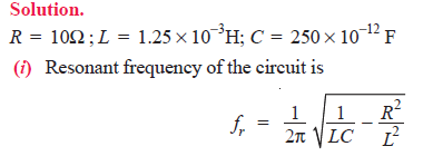
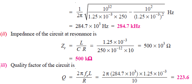
Q1. A parallel resonant circuit has a capacitor of 250pF in one branch and inductance of 1.25mH plus a resistance of 10Ω in the parallel branch. Find (i) resonant frequency (ii) impedance of the circuit at resonance (iii) Q-factor of the circuit.
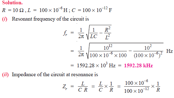
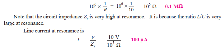
Q2. A parallel resonant circuit has a capacitor of 100 pF in one branch and inductance of 100 μH plus a resistance of 10 Ω in parallel branch. If the supply voltage is 10 V, calculate (i) resonant frequency (ii) impedance of the circuit and line current at resonance.
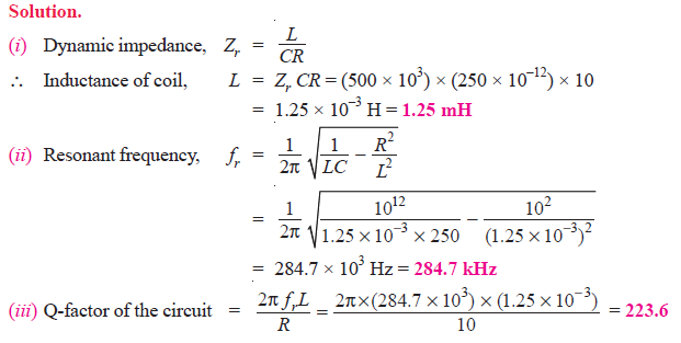
Q3. The dynamic impedance of a parallel resonant circuit is 500 kΩ. The circuit consists of a 250 pF capacitor in parallel with a coil of resistance 10Ω. Calculate (i) the coil inductance (ii) the resonant frequency and (iii) Q-factor of the circuit.
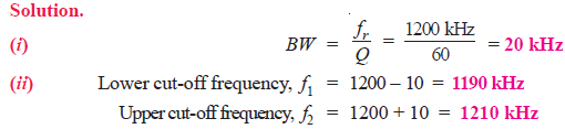
Q4. The Q of a tuned amplifier is 60. If the resonant frequency for the amplifier is 1200 kHz, find (i) bandwidth and (ii) cut-off frequencies.
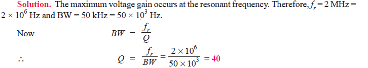
Q5. A tuned amplifier has maximum voltage gain at a frequency of 2 MHz and the bandwidth is 50 kHz. Find the Q factor.
Q6. It is desired to obtain a bandwidth of 200 kHz at an operating frequency of 10 MHz using a double tuned circuit. What value of co-efficient of coupling should be used ?
![]()
Q7. In the circuit shown in Fig.1, C = 500 pF and the coil has L = 50.7 μH and R = 10Ω and RL = 1 MΩ. Find (i) the resonant frequency (ii) d.c. load and a.c. load.
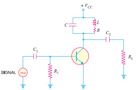
Fig.1

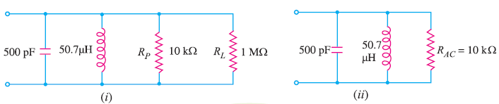
Fig.2
The equivalent circuit is shown in Fig.2 (i). This further reduces to the circuit shown in Fig. 2 (ii).
![]()
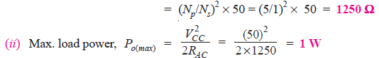
Q8. Calculate (i) a.c. load (ii) maximum load power in the circuit shown in Fig. 3.
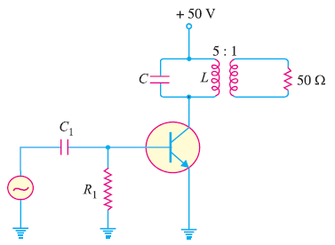
Fig.3
Solution.
(i) A.C. load, RAC = Reflected load resistance seen by the collector
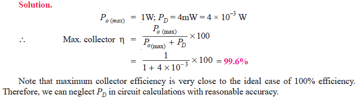
Q9. In the above example, if power dissipation of the transistor is 4 mW, find the maximum collector efficiency.