What is a Band Pass Filter ? Draw and explain the frequency response of a band pass filter
Last Updated on October 26, 2015 by Sasmita
Band Pass Filter
Sometimes it is desirable to only pass a certain range of frequencies that do not begin at 0 Hz, (DC) or end at some upper high frequency point but are within a certain range or band of frequencies, either narrow or wide and attenuate other frequencies on both sides of this pass band.
This pass band is called the bandwidth of the filter.
This can be achieved by cascading a low-pass filter capable of transmitting all frequencies upto the cut off frequency fL to a high pass filter capable of transmitting all frequencies higher than the cut off frequency fH ,with fH>fL .
The system so developed will be capable of transmitting frequencies between fL and fH and attenuate all other frequencies below fL and above fH and this new type of passive filter arrangement is commonly known as a Band Pass Filter or BPF .
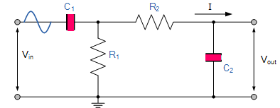
The circuit of a R-C band pass filter is shown in fig. below :
The pass band or bandwidth of this filter is given by :
Bandwidth = fH – fL
The values of fL and fH are given by the following equations :


Frequency Response of Band Pass Filter
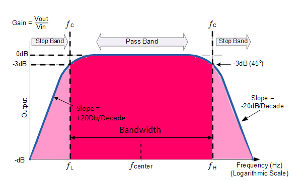
The Bode Plot or frequency response curve of band pass filter is shown in the above fig.
Here the signal is attenuated at low frequencies with the output increasing at a slope of +20dB/Decade (6dB/Octave) until the frequency reaches the “lower cut-off” point ƒL. At this frequency the output voltage is again 1/√2 = 70.7% of the input signal value or -3dB (20 log (Vout/Vin)) of the input.
The output continues at maximum gain until it reaches the “upper cut-off” point ƒH where the output decreases at a rate of -20dB/Decade (6dB/Octave) attenuating any high frequency signals.
The point of maximum output gain is generally the geometric mean of the two -3dB value between the lower and upper cut-off points and is called the “Centre Frequency” or “Resonant Peak” value ƒr. This geometric mean value is calculated as being ƒr 2 = ƒH x ƒL.
A band pass filter is regarded as a second-order (two-pole) type filter because it has “two” reactive components within its circuit structure, then the phase angle will be twice that of the previously seen first-order filters, ie, 180o. The phase angle of the output signal LEADS that of the input by+90o up to the centre or resonant frequency, ƒr point were it becomes “zero” degrees (0o) or “in-phase” and then changes to LAG the input by -90o as the output frequency increases.
