What is a differential amplifier ? Discuss the operation of a differential amplifier
Last Updated on September 27, 2015 by Sasmita
Differential Amplifier
A differential amplifier is a circuit that can accept two input signals and amplify the difference between these two input signals.
Fig.1 shows the block diagram of a differential amplifier .

There are two input voltages v1 and v2.
This amplifier amplifies the difference between the two input voltages.
Therefore the output voltage is,
![]()
Where A is the voltage gain of the amplifier.
Basic circuit of Differential Amplifier
Fig.2 (i) shows the basic circuit of a differential amplifier.

It consists of two transistors Q1 and Q2 that have identical (ideally) characteristics.
They share common positive supply VCC, common emitter resistor RE and common negative supply VEE.
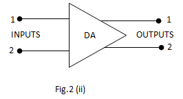
Fig.2(ii) shows the symbol of differential amplifier.
The following points may be noted about the differential amplifier :
- The differential amplifier (DA) is a two-input terminal device using at least two transistors. There are two output terminals marked 1(v out 1 ) and 2 (v out 2 ).
- The transistors Q1 and Q2 are matched so that their characteristics are the same. The collector resistors (RC1 and RC2 ) are also equal. The equality of the matched circuit components makes the DA circuit arrangement completely symmetrical.
- We can apply signals to a differential amplifier in the following two ways :
a) The signal is applied to one input of DA and the other input is grounded. In this case it is called single-ended input arrangement.
b) The signals are applied to both inputs of DA. In this case it is called dual-ended or double-ended input arrangement.
4. We can take output from DA in the following two ways :
a) The output can be taken from one of the output terminals and the ground. In this case it is called single-ended output arrangement.
b) The output can be taken between the two output terminals (i.e. between the collectors of Q1 and Q2). In this case it is called double-ended output arrangement or differential output.
5. Generally the differential amplifier (DA) is operated for single-ended output.
Operation of Differential Amplifier
For simplicity, we shall discuss the operation of single-ended input and double-ended output DA.
Case – 1:
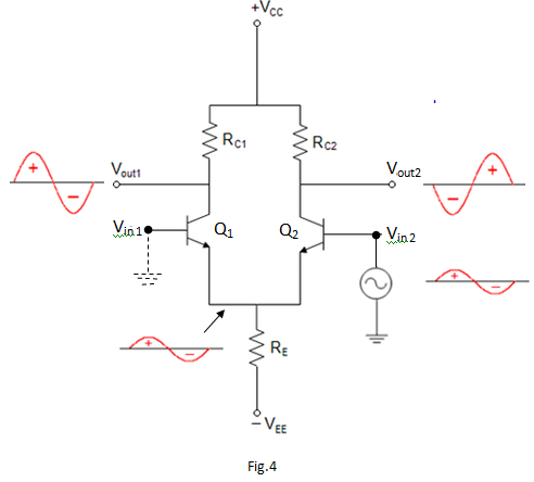
Suppose the signal is applied to input 1 (i.e. base of transistor Q1) and input 2(i.e.base of transistor Q2 ) is grounded as shown in fig.3.

The transistor Q1 will act in two ways: as a common emitter amplifier and as a common collector amplifier.
As a common emitter amplifier, the input signal to Q1 will appear at output 1 (i.e. collector of Q1) as amplified inverted signal.
As a common collector amplifier, the signal appears on the emitter of Q1 in phase with the input and only slightly smaller.
Since the emitters of Q1 and Q2 are common, the emitter signal becomes input to Q2.
Therefore, Q2 functions as a common base amplifier.
As a result, the signal on the emitter Q2 will be amplified and appears on output 2 (i.e. collector of Q2) in phase with the emitter signal and hence in phase with the input signal (signal at input 1). This is shown in Fig.4.
Case – 2:
Now suppose the signal is applied to input 2 (i.e. base of transistor Q2) and input 1 is grounded.
Now Q2 acts as a common emitter amplifier and common collector amplifier while Q1 acts as a common base amplifier.
Therefore, an inverted and amplified signal appears at output 2 and non-inverted, amplified signal appears at output 1. This is shown in Fig.4.
When signal applied to the input of DA produces no phase shift in the output, it is called non-inverting input. In other words, for non-inverting input, the output signal is in phase with the input signal.
When the signal applied to the input of DA produces 1800 phase shift, it is called inverting input. In other words, for inverting input, the output signal is 1800 out of phase with the input signal.