What Is A Zener Diode And How It Is Used As A Voltage Stabiliser
Last Updated on January 29, 2019 by Sasmita
What Is A Zener Diode
When the reverse bias voltage on a normal crystal diode is increased, a point known as Knee point is reached at a voltage known as breakdown voltage, when the reverse current increases sharply to a high value. This breakdown voltage is also known as Zener Voltage and the sharp increase in current is known as Zener current.
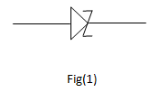
The breakdown voltage of a diode depends on the amount of doping. In a heavily doped diode, the depletion layer is thin, so the breakdown of the junction occurs at a lower reverse bias voltage. On the other hand, a lightly doped diode has a higher breakdown voltage. When an ordinary crystal diode is properly doped so as to have a sharp breakdown voltage ,it is known as zener diode. Fig(1) shows the symbol of a zener diode.
A zener diode is always used in reverse biased state. It has sharp breakdown voltage known as Zener voltage VZ. When forward biased ,it behaves just like ordinary crystal diode. Fig(2) shows the characteristics of a zener diode.
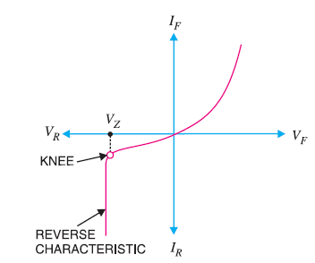
Fig. 2
Equivalent Circuit of a Zener Diode
Case 1. On State
When the reverse voltage across a zener diode is equal to or higher than the breakdown voltage VZ , the current increase very sharply.
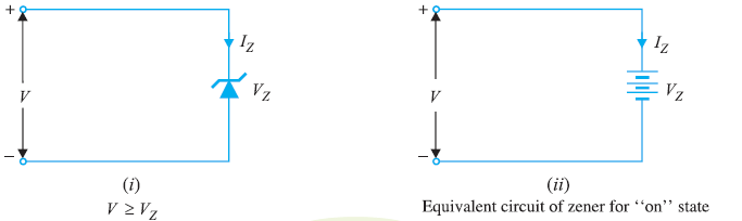
Fig. 3
In this state, voltage across the zener diode is constant at VZ irrespective of the change in current though it.
Therefore, in breakdown region an ideal zener diode acts as a battery of voltage VZ , and the zener diode is said to be in “ON” State.
Case 2.OFF State:
When the reverse voltage across the zener diode is less than VZ but greater than 0v, the zener diode is in the “OFF”State. Under such state, the zener diode can be replaced by an Open circuit.
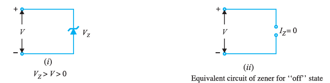
Fig. 4
Zener Diode as Voltage Stabiliser
A zener diode can be used as a voltage stabiliser or voltage regulator to provide a constant voltage from a source whose voltage may vary over a particular range.
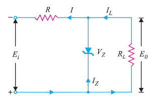
Fig. 5
The circuit connection is shown in fig(5).
The zener diode of zener voltage VZ is connected reversly across the load resistance RL across which constant output voltage EO is required.
The series resistance R is used to absorb the output voltage fluctuations, so as to maintain constant output voltage across RL .
When the circuit is properly designed, the output voltage EO remains constant even though the input voltage Ei and load resistance RL may vary over a wide range.
Case 1: Ei Variable and RL constant
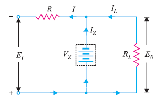
Fig.6
Suppose the input voltage Ei increases, since the zener is in the breakdown region, the zener diode is equivalent to a battery of voltage VZ and the output voltage remains constant at VZ ( EO =VZ).
The excess voltage is dropped across R. This will cause an increase in the value of total current I. The zener will conduct the increase of current in I, while the load current remains constant.
Hence the output voltage remains constant irrespective of the change in input voltage Ei
Summary(Case 1)
Suppose Ei increases
Since zener is in breakdown region, VZ remains constant
EO = VZ
So EO remains constant
Excess voltage drops across R
So I increases, since IL remains constant, IZ increases
![]()
So the excess current is conducted by the zener diode and EO remains constant irrespective of the change in Ei
Case 2: Ei Constant and RL Vaiable
Now suppose the input voltage Ei is constant but RL decreases
Since the zener diode is in breakdown region , voltage across it will remain constant at VZ.
As the output voltage EO is equal to the zener voltage, So EO will also remain constant at VZ.
When RL decreases ,in order to maintain EO constant, current through the load resistance IL will increase.
Since Ei is constant, total current I is also constant. So the increase in load current IL will come from a decrease in zener current IZ .
![]()
Voltage drop across R = Ei – EO
Current through R , I = IZ + IL