What is Modulation Index and Transmission Efficiency of an AM wave ? Explain The Evaluation of Modulation Index and Transmission Efficiency
Last Updated on November 25, 2015 by Sasmita
Modulation Index or Modualation Factor
In AM wave, the modulation index (m) is defined as the ratio of amplitudes of the modulating and carrier waves as under :

When ![]() ,the modulation index ‘m’ has values between 0 and 1 and no distortion is introduced in the AM wave .
,the modulation index ‘m’ has values between 0 and 1 and no distortion is introduced in the AM wave .
But if ![]() , then ‘m’ is greater than 1 . This will distort the shape of the AM signal. The distortion is called as ‘over modulation’ .
, then ‘m’ is greater than 1 . This will distort the shape of the AM signal. The distortion is called as ‘over modulation’ .
The modulation index is also called as modulation factor, modulation coefficient or degree of modulation .
However, this modulation index is expressed as percentage and it is called as ‘percentage modulation’ .
Therefore,
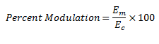
Here, it may be noted that m is a dimensionless quantity .
Linear Modulation and Over Modulation
Depending on the value of percentage modulation (m), the AM wave may be classified into following two categories :
- Linear modulation
- Over modulation
Linear Modulation
If ![]() or if the percentage modulation is less than 100, then the type of modulation is linear amplitude modulation.
or if the percentage modulation is less than 100, then the type of modulation is linear amplitude modulation.
The waveforms of AM waves with linear modulation have been shown in fig.1 (a) and (b) respectively .


Fig 1 (a) Fig 1(b)
Over Modulation
If ![]() , i.e., if the percentage modulation is greater than 100%, then the type of modulation is called as over modulation.
, i.e., if the percentage modulation is greater than 100%, then the type of modulation is called as over modulation.
Since m > 1 , the envelope can sometimes reverse the phase as shown in fig.1 (c) .
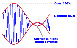
Fig 1(c)
Over modulation introduces envelope distortion . Therefore, it should be avoided .
Evaluation of Modulation Index
The modulation index can be measured using the following two methods :
- Using the AM signal as it is
- Using the trapezoidal display of the AM wave
Modulation Index Evaluation using the AM Wave
If the AM signal is displayed on the screen of a cathode ray oscilloscope (CRO) , it appears to be as shown in fig.2 .
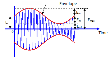
Fig 2
The x-axis represents the time and y-axis represents the amplitude in volts.
The dotted line which represents the envelope of AM signal does not appear on the screen .
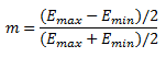
In order to calculate modulation index ‘m’ which is :
we must express Em and Ec in terms of Emax and Emin .
From the fig.1, we can write,
 ……………..(1)
![]() …………………(2)
…………………(2)
Substituting the value of Em from equation (1) into equation (2), we get
![]()
 …………………..(3)
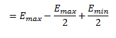
But ,
Now, substituting the values of Em and Ec from equation (1) and (3), we get
Hence,
 ………………………(4)
This is the required expression.
Evaluation of modulation Index Using Trapezoidal Display
The set up for evaluating the modulation index using trapezoidal display has been shown in fig.3(a) and the corresponding waveforms have been shown in fig 3(b).
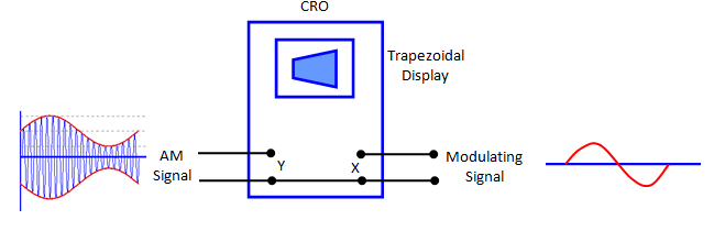
Fig 3 (a)
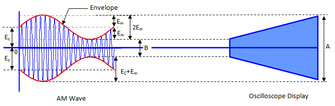
Fig 3(b)
In this method, the AM signal is connected to vertical deflection plates of the oscilloscope .
The display on the screen of the oscilloscope is of trapezoidal shape as shown in fig 3 (b).
From fig.3 , we can write
![]() ………………………………(5)
………………………………(5)
![]() ………………………..(6)
………………………..(6)
Therefore, adding equations (5) and (6), we obtain
![]()
![]() ……………………(7)
……………………(7)
And subtraction of equations (5) and (6) yield
![]()
![]() ……………………….(8)
……………………….(8)
The modulation index,
Substituting the value of Em and Ec from equation (7) and (8), we get
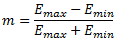
 ………………………..(9)
Thus, it is possible to obtain the modulation index by measuring the length A and B .
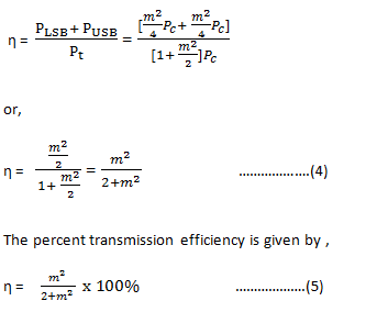
Transmission Efficiency
Transmission efficiency of an AM wave is the ratio of the transmitted power which contains the information (i.e. the total sideband power) to the total transmitted power.
Why should ‘m’ be as high as possible?
The higher percentage of modulation is preferred for strong and more intelligible received signal, because higher percentage of modulation means higher value of modulation index m. With increased value of m, the transmitted power Pt by the AM transmitter will increase as,
![]()
![]()
Thus it is ensured that the received signal will be strong by having a higher percentage of modulation. Moreover a strong signal is less likely to get contaminated or lost in the noise, hence becomes more intelligible.