Describe the circuit and operation of an Active Low Pass Filter with neat diagram
Last Updated on October 26, 2015 by Sasmita
Active Low Pass Filter
In our previous Low Pass Filter tutorials, we discussed about different types of passive low pass filter circuits, which are made using passive components such as resistors, capacitors, and inductors, across a sinusoidal input signal.
The main disadvantage of passive filters is that the amplitude of the output signal is less than that of the input signal, i.e, the gain is never greater than unity and that the load impedance affects the filters characteristics.
In case of passive filter circuits containing multiple stages, this loss in signal amplitude also known as attenuation can become quiet severe.
One way of restoring or controlling this loss of signal is by using amplification through the use of Active Filters.
Active Filters contain active components such as operational amplifiers, transistors or FET’s within their circuit design.
They draw their power from an external power source and use it to boost or amplify the output signal.
The main difference between a “passive filter” and an “active filter” is amplification.
An active filter generally uses an operational amplifier (op-amp) within its design and in our Operational amplifier tutorial we saw that an Op-amp has a high input impedance, a low output impedance and a voltage gain determined by the resistor network within its feedback loop.
The simplest form of a low pass active filter is to connect an inverting or non-inverting amplifier, the same as those discussed in the application of OP-amp tutorial, to the basic RC low pass filter circuit as shown below.
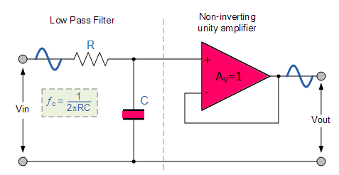
Its principle of operation and frequency response is exactly the same as those for the previously seen passive filter, the only difference this time is that it uses an op-amp for amplification and gain control.
This low pass active filter, consists of a passive RC filter stage which provides a low frequency path to the input of a non-inverting operational amplifier.
The operational amplifier is configured as a voltage-follower (Buffer) giving it a DC gain of one, Av = +1 (which is less than unity in case of passive RC filter).
The advantage of this configuration is that the op-amps high input impedance prevents excessive loading on the filters output while its low output impedance prevents the filters cut-off frequency point from being affected by changes in the impedance of the load.
The main disadvantage of this filter is that it has no voltage gain above one.
However, although the voltage gain is unity the power gain is very high as its output impedance is much lower than its input impedance. If a voltage gain greater than one is required we can use the following filter circuit.
Active Low Pass Filter with Amplification
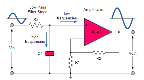
The frequency response of the circuit will be the same as that for the passive RC filter, except that the amplitude of the output is increased by the pass band gain, AF of the amplifier.
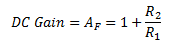
For a non-inverting amplifier circuit, the magnitude of the voltage gain for the filter is given as a function of the feedback resistor ( R2 ) divided by its corresponding input resistor ( R1 ) value and is given as:
Therefore, the gain of an active low pass filter as a function of frequency will be:
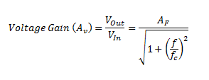
Where
AF = pass band gain of the filter
ƒ = frequency of the input signal in Hz
ƒc = the cut-off frequency in Hz
Thus, the operation of a low pass active filter can be verified from the frequency gain equation above as:
- At very low frequencies, ƒ < ƒc

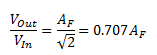
2. At the cut-off frequency, ƒ = ƒc
3. At very high frequencies, ƒ > ƒc

Thus, the Active Low Pass Filter has a constant gain AF from 0 Hz to the high frequency cut-off point, fc. At fc the gain is 0.707AF, and after fc it decreases at a constant rate as the frequency increases.