Direct Coupled Transistor Amplifier with Circuit Diagram
Last Updated on October 1, 2015 by Sasmita
Direct Coupled Transistor Amplifier
There are many applications in which extremely low frequency signals i.e. below 10 Hz are to be amplified, for example, amplifying photo-electric current, thermo-couple current etc.
In such applications, use of coupling devices such as capacitors and transformers makes such amplifiers bulky due to the large electrical size of these components at low frequencies.
Hence, in such cases, one stage is directly connected to the next stage without any intervening coupling device. This type of coupling is known as direct coupling.
Working of Direct Coupled Transistor Amplifier
The figure below shows the circuit of a three-stage direct coupled amplifier.
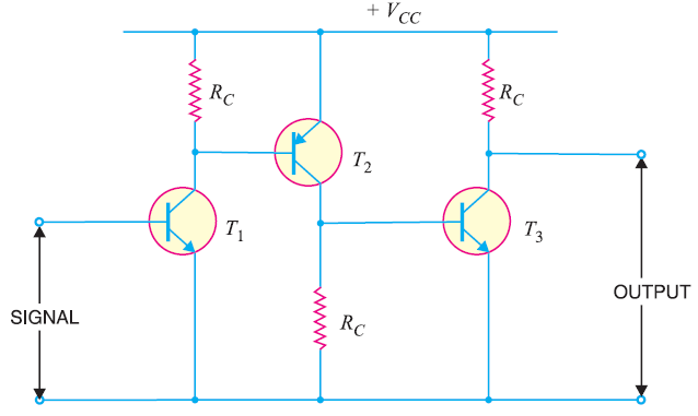
As you can see from the above fig. this circuit uses complementary transistors, which makes the circuit stable with respect to temperature changes.
The first stage uses npn transistor, the second stage uses pnp transistor and so on.
The output from the collector of first transistor T1 is fed to the second transistor T2 and so on.
The weak signal is applied to the input of first transistor T1 . Due to transistor action, an amplified output is obtained across the collector load RC of T1 .
Now this voltage drives the base of the second transistor T2 and produce amplified output at its collector load.
In this way, direct coupled amplifier raises the strength of weak signal.
Advantages of Direct Coupled Transistor Amplifier
- Circuit is simple because of minimum use of resistors.
- Cost is low because of the absence of expensive coupling devices.
Disadvantages of Direct Coupled Transistor Amplifier
- This amplifier can not be used for amplifying high frequency signals.
- The operating point is shifted due to temperature variations.
You Might Like The Following Articles