Discuss the essentials of a transistor Oscillator . Explain the action of tuned collector oscillator , Colpitt’s oscillator and Hartley oscillator
Last Updated on January 9, 2020 by Sasmita
Transistor Oscillator
A transistor with proper positive feedback can act as an oscillator. It can generate oscillations without any external signal source. Fig.1 shows a transistor amplifier with positive feedback.

Fig.1
A positive feedback amplifier is one that produces a feedback voltage (Vf) that is in phase with the input signal.
As we can see this condition is met in the circuit shown in fig.1. A phase shift 180o is produced by the amplifier and a further phase shift of 180o is introduced by the feedback network. Consequently, the signal is shifted by 360o and fed to the input. That means feedback voltage is in phase with the input signal.
The circuit shown in fig.1 is producing oscillations in its output, but with the application of an input signal, which is inconsistent with the definition of an oscillator.
When we open the switch S of fig.1 we get the circuit as shown in fig.2.

Fig.2
The input signal Vin is now removed. However the feedback signal Vf is still applied to the input. The amplifier will respond to this feedback signal in the same way that it did to Vin.
The feedback signal Vf will be now amplified and send to the output.
The feedback network sends a portion of the output back to input.
Therefore, the amplifier receives another input cycle and another output cycle is produced.
This process will continue so long as the amplifier is turned on.
Therefore, the amplifier will produce sinusoidal output with no external signal source.
The following points may be noted now:
- A transistor amplifier with proper positive feedback will work as an oscillator.
- The circuit needs only a quick trigger signal to start the oscillations. Once the oscillations have started, no external signal source is needed.
- In order to get continuous undamped output from the circuit, the following condition must be met:
mv Av =1
Where mv = voltage gain of amplifier without feedback
Av = feedback fraction
This relation is called Barkhausen criterion .
Barkhausen Criterion
Barkhausen criterion is that in order to produce continuous undamped oscillations at the output of an amplifier, the positive feedback should be such that :
mv Av =1
Once this condition is set in the positive feedback amplifier, continuous undamped oscillations can be obtained at the output.
Essentials of Transistor Oscillator
Fig.3. shows the block diagram of an oscillator. Its essential components are:

Fig.3
(i) Tank Circuit:
It consists of inductance (L) connected in parallel with capacitor (C) . The frequency of oscillations in the circuit depends upon the values L and C.
(ii) Transistor amplifier:
The transistor amplifier receives d.c. power from the battery and changes it into a.c. power for supplying to the tank circuit. The oscillations occurring in the tank circuit are applied to the input of the transistor amplifier. Because of the amplifying nature of the transistor, we get increased output of these oscillations. This amplified output of oscillations is due to the d.c. power supplied by the battery. The output of the transistor can be supplied to the tank circuit to meet the losses.
(iii) Feedback circuit:
The feedback circuit supplies a part of collector energy to the tank circuit in correct phase to aid the oscillations i.e. it provides positive feedback.
Different types of Transistor Oscillators
All oscillators under different names have similar function i.e. they produce continuous undamped output. However, the major difference between these oscillators lies in the method by which energy is supplied to the tank circuit to meet the losses.
The following are the transistor oscillators commonly used at various places in electronic circuit:
- Tuned collector oscillator
- Colpitt’s Oscillator
- Hartley Oscillator
- Phase shift Oscillator
- Wien Bridge Oscillator
- Crystal Oscillator
Tuned Collector Oscillator
Fig.4 shows the circuit of tuned collector oscillator.

Fig.4
It contains tuned circuit L1-C1 in the collector and hence it is named so.
The frequency of oscillations depends upon the values of L1 and C1 and is given by :
 …………………..(i)
The feedback coil L2 in the base circuit is magnetically coupled to the tank circuit coil L1. In practice L1 and L2 form the primary and secondary of the transformer.
The biasing is provided by the potential divider arrangement.
The capacitor C2 connected in the base circuit provides low reactance path to the oscillations.
Circuit Operation:
When VCC is applied to the circuit, collector current starts increasing and charges the capacitor C1.
When this capacitor is fully charged, it discharges through coil L1, setting up oscillations of frequency determined by exp.(i).
These oscillations induce some voltage in coil L2 by mutual induction.
The frequency of voltage in coil L2 is the same as that of tank circuit but its magnitude depends upon the number of turns of L2 and coupling between L1 and L2.
The voltage across L2 is applied between base and emitter and appears in the amplified form in the collector circuit, thus overcoming the losses occurring in the tank circuit.
The number of turns of L2 and coupling between L1 and L2 are so adjusted that oscillations across L2 are amplified to a level just sufficient to supply losses to the tank circuit.
A phase shift of 180o is created between the voltage of L1 and L2 due to transformer action. A further phase shift of 180o takes place between base-emitter and collector circuit due to transistor properties. As a result, the energy feedback to the tank circuit is in phase with the generated oscillations.
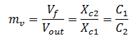
Colpitt’s Oscillator
Fig(5) shows the circuit diagram of a Colpitt’s oscillator.

Fig.5
It consists of two capacitors C1 and C2, placed across a common inductor L and the centre of the two capacitors is tapped.
The tank circuit is made up of C1, C2 and L.
The frequency of oscillations is determined by the values of C1, C2 and L and is given by:
 ………………………..(i)
Where,

Circuit Operation:
When the circuit is turned on, the capacitor C1and C2are charged.
The capacitors discharge through L, setting up oscillations of frequency determined by exp.(i).
The output voltage of the amplifier appears across C1 and feedback voltage is developed across C2.
The voltage across it is 180o out of phase with the voltage developed across C1(Vout) as shown in fig(6).
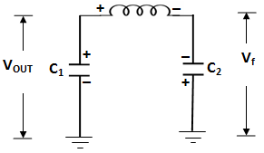
Fig.6: Feedback Circuit
It can be noted that voltage feedback to the transistor provides positive feedback. A phase shift of 180o is produced by the transistor and a further phase shift of 180o is produced by C1 – C2 voltage divider.
In this way, feedback is properly phased to produce continuous undamped oscillations.
Feedback Fraction: The amount of feedback voltage in Colpitt’s oscillator depends upon feedback fraction mv of the circuit. For this circuit,
Feedback fraction,
Or,

Hartley Oscillator
The Hartley oscillator is similar to Colpitt’s oscillator with minor modifications.
Instead of using tapped capacitors, two inductors L1 and L 2are placed across a common capacitor C.
The centre of the inductors is tapped as shown in fig(7).

Fig.7
The tank circuit is made up of L1, L2 and C .
The frequency of oscillations is determined by the values of L1, L2 and C and is given by:
 …………………………..(i)
Where,
![]()
Here M= mutual inductance between L1 and L2
Circuit Operation:
When the circuit is turned on, the capacitor is charged.
When the capacitor is fully charged, it discharges through coils L1 and L2 ,setting up oscillations of frequency determined by exp(i).
The output voltage of the amplifier appears across L1and feedback voltage across L2.
The voltage across L2 is 180o out of phase with the voltage developed across L1, as shown in fig(8).
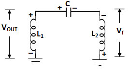
Fig.8
It can be noted that voltage feedback to transistor provides positive feedback.
A phase shift of 180o is produced by the transistor and a further phase shift of 180o is produced by L1– L2 voltage divider.
In this way, feedback is properly phased to produce continuous undamped oscillations.
Feedback Fraction: In Hartley oscillator, the feedback voltage is across L2 and output voltage is across L1.
Feedback Fraction,
Or,

You Might Like The Following Articles
- What is a Transistor ? Describe the Transistor Action in Detail . Explain the Operation of Transistor as an Amplifier
- Explain the construction and working of a JFET. What is the difference between a JFET and a BJT
- Describe the output Characteristics and transfer characteristics of JFET . Explain different methods of biasing of a JFET
- Explain the construction and working of MOSFET
- Unijunction Transistor
- Discuss the essentials of a transistor Oscillator . Explain the action of tuned collector oscillator , Colpitt’s oscillator and Hartley oscillator