Glow Tube Voltage Regulator
Last Updated on October 1, 2015 by Sasmita
Glow Tube Voltage Regulator
A glow tube voltage regulator uses a particular characteristic of a glow tube. When a glow tube (cold cathode gas diode) is operated in the normal glow region, the voltage across the tube remains constant over a wide range of tube current. It is this characteristic that is used by the glow tube voltage regulator .
Circuit Diagram of Glow Tube Voltage Regulator
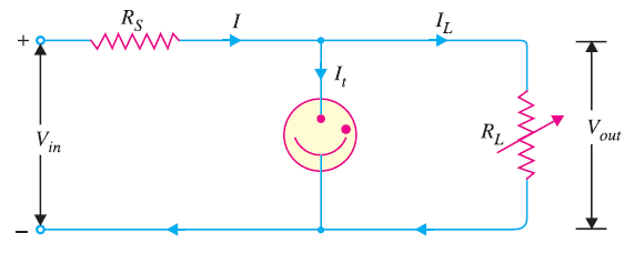
The unregulated d.c. input voltage must exceed the striking voltage of the tube. Once the gas in the tube ionises, the voltage across the tube and the load will drop to the ionising voltage. The tube will maintain constant voltage so long as the input d.c. voltage is greater than this value. The resistance RS is used to limit the input current.
Working of Glow Tube Voltage Regulator
The glow tube will maintain constant voltage across the load inspite of the changes in load current or input voltage. Now, should the load decrease, the output voltage would tend to increase. The glow tube will draw more current *without any increase in the output voltage. Meanwhile, the drop in load current is offset by the increase in tube current and the current through RS remains constant. As output voltage = Vin − IRS , therefore, output voltage remains unchanged. Similarly, the circuit will maintain constant output voltage if the input voltage changes. Suppose the input voltage decreases due to any reason. This would result in less current flow through the glow tube.
Consequently, the voltage drop across RS decreases, resulting in constant voltage across the load.
You Might Like The Following Articles
- Regulated DC Power Supply
- DC Voltage Regulator Circuit
- Zener Diode Voltage Regulator
- Transistor Series Voltage Regulator
- Series Feedback Voltage Regulator
- Transistor Shunt Voltage Regulator
- Shunt Feedback Voltage Regulator
- Glow Tube Voltage Regulator
- Series Triode Voltage Regulator
- Series Double Triode Voltage Regulator
- IC Voltage Regulator