Zener Diode Voltage Regulator
Last Updated on October 1, 2015 by Sasmita
Zener Diode Voltage Regulator
The zener diode voltage regulator is based on a particular characteristic of zener diodes. When the zener diode is operated in the breakdown or zener region, the voltage across it is substantially constant for a large change of current through it. And it is this characteristic of a zener diode that permits it to be used as a voltage regulator.
Circuit Diagram of Zener Diode Voltage Regulator
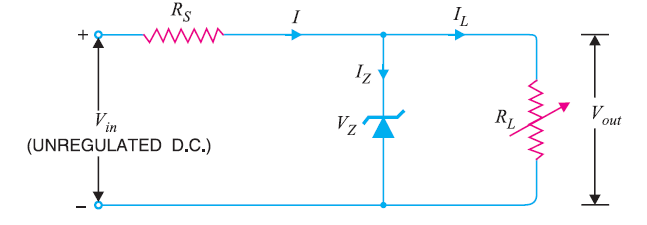
As long as input voltage Vin is greater than zener voltage VZ , the zener operates in the breakdown region and maintains constant voltage across the load. The series limiting resistance RS limits the input current.
The zener will maintain constant voltage across the load inspite of changes in load current or input voltage. As the load current increases, the zener current decreases so that current through resistance RS is constant. As output voltage = Vin – IRS, and I is constant, therefore, output voltage remains unchanged. The reverse would be true shouldthe load current decrease. The circuit will also correct for the changes in input voltages. Should the input
voltage Vin increase, more current will flow through the zener, the voltage drop across RS will increase but load voltage would remain constant. The reverse would be true should the input voltage decrease.
Drawbacks of Zener Diode Voltage Regulator
- It has low efficiency for heavy load currents. It is because if the load current is large, there will be considerable power loss in the series limiting resistance.
- The output voltage slightly changes due to zener impedance as Vout = VZ + IZ ZZ. Changes in load current produce changes in zener current. Consequently, the output voltage also changes. Therefore, the use of this circuit is limited to only such applications where variations in load current and input voltage are small.
Conditions Necessary for The Proper Operation of Zener Diode Voltage Regulator
- The zener must operate in the breakdown region or regulating region i.e. between IZ (max) and IZ (min). The current IZ (min) (generally 10 mA) is the minimum zener current to put the zener diode in the ON state i.e. regulating region. The current IZ (max) is the maximum zener current that zener diode can conduct without getting destroyed due to excessive heat.
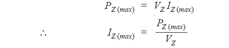
- The zener should not be allowed to exceed maximum dissipation power otherwise it will be destroyed due to excessive heat. If maximum power dissipation of a zener is PZ (max) and zener voltage is VZ, then,
- There is a minimum value of RL to ensure that zener diode will remain in the regulating region i.e. breakdown region. If the value of RL falls below this minimum value, the proper voltage will not be available across the zener to drive it into the breakdown region.
You Might Like The Following Articles
- Regulated DC Power Supply
- DC Voltage Regulator Circuit
- Zener Diode Voltage Regulator
- Transistor Series Voltage Regulator
- Series Feedback Voltage Regulator
- Transistor Shunt Voltage Regulator
- Shunt Feedback Voltage Regulator
- Glow Tube Voltage Regulator
- Series Triode Voltage Regulator
- Series Double Triode Voltage Regulator
- IC Voltage Regulator