Transistor Series Voltage Regulator
Last Updated on October 1, 2015 by Sasmita
Transistor Series Voltage Regulator
In the figure below, you can see a simple series voltage regulator that is using a transistor and Zener diode. 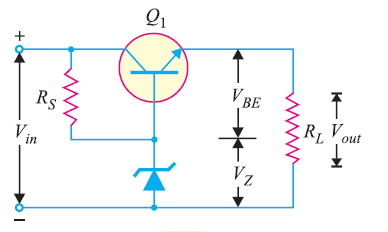
You can see in the figure that the load current is passing through the series transistor Q1 & that’s the reason why we call the circuit a series voltage regulator . You can see that we feed the unregulated d.c. supply through the input terminals so that we can get the regulated across the load. Here, the zener diode is providing the reference voltage.
Operation of Transistor Series Voltage Regulator
The base voltage of transistor Q1 is held to a relatively constant voltage across the Zener diode. For example, if 8V zener (i.e., VZ = 8V) is used, the base voltage of Q1 will remain approximately 8V. Hence , Vout = VZ – VBE
Case 1 : Output Voltage Decreases
Under this circumstance , the increased base-emitter voltage will cause transistor Q1 to conduct more, thus increasing the output voltage. Hence, the output voltage will be maintained at a constant level.
Case 2 : Output Voltage Increases
Under this circumstance , the decreased base-emitter voltage will cause Q1 to conduct less, thus reducing the output voltage. Hence, the output voltage will be maintained at a constant level.
Advantage of Transistor Series Voltage Regulator
The advantage of this circuit is that the changes in zener current are reduced by a factor ß. Hence, the effect of zener impedance is tremendously reduced and we get a more stabilised output.
Disadvantage of Transistor Series Voltage Regulator
- Despite the fact that changes in zener current are reduced to a considerable extent, the output is not absolutely constant. This happens because both VBE and VZ decrease with the increase in room temperature.
- It is not easy to change the output voltage as no such means is provided.
You Might Like The Following Articles
- Regulated DC Power Supply
- DC Voltage Regulator Circuit
- Zener Diode Voltage Regulator
- Transistor Series Voltage Regulator
- Series Feedback Voltage Regulator
- Transistor Shunt Voltage Regulator
- Shunt Feedback Voltage Regulator
- Glow Tube Voltage Regulator
- Series Triode Voltage Regulator
- Series Double Triode Voltage Regulator
- IC Voltage Regulator